Advertisement
Installation Manual
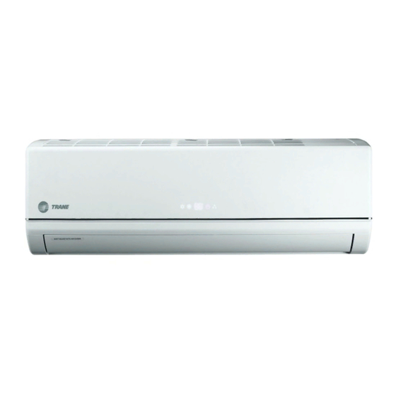
Split System (R-410A)
Inverter Unit 15 SEER
9,000 to 24,000 BTU/Hr - 60 Hz
Cooling only
Heat pump
Only qualified personnel should install and service the equipment. The installation, starting up, and servicing
of heating, ventilating and air-conditioning equipment can be hazardous and requires specific knowledge and
training. Improperly installed, adjusted or altered equipment by an unqualified person could result in death or
serious injury. When working on the equipment, observe all precautions in the literature and on the tags,
stickers and labels that are attached to the equipment.
March 2015
Indoor Unit
4MYW4-A
4MXW4-A
WARNING
MS-SVN046A-EN
Outdoor Unit
4TYK4-A
4TXK4-A
Advertisement

Related Manuals for Trane 4MYW4509A1


Summary of Contents for Trane 4MYW4509A1
- Page 1 Installation Manual Split System (R-410A) Inverter Unit 15 SEER 9,000 to 24,000 BTU/Hr - 60 Hz Indoor Unit Outdoor Unit Cooling only 4MYW4-A 4TYK4-A Heat pump 4MXW4-A 4TXK4-A WARNING Only qualified personnel should install and service the equipment. The installation, starting up, and servicing of heating, ventilating and air-conditioning equipment can be hazardous and requires specific knowledge and training.
- Page 3 All technicians who handle refrigerants must be refrigerant into the system. For specific handling certified. The Federal Clean Air Act (Section 608) sets forth concerns with R-410A, contact your local Trane the requirements for handling, reclaiming, recovering and representative.
-
Page 4: Table Of Contents
Content Content General Information ............5 Accessories . -
Page 5: General Information
Warranty is based on the general terms and conditions by country. The warranty is voided if the equipment is modified or repaired without the written approval of The Trane Company, and if the operating limits are exceeded or if the control system or the electric wiring is modified. -
Page 6: Accessories
Accessories Accessories 0~10 MS-SVN046A-EN... - Page 7 Model Numbers Model Numbers High Efficiency (15 SEER), R410A - 60Hz Cooling Only Indoor Units 4MYW4509A1 4MYW4512A1 4MYW4518A1 4MYW4524A1 Outdoor Units 4TYK4509A1 4TYK4512A1 4TYK4518A1 4TYK4524A1 Heat Pump Indoor Units 4MXW4509A1 4MXW4512A1 4MXW4518A1 4MXW4524A1 Outdoor Units 4TXK4509A1 4TXK4512A1 4TXK4518A1 4TXK4524A1 MS-SVN046A-EN...
- Page 8 Installation Installation Names and functions of each part MS-SVN046A-EN...
-
Page 9: Installation Location
Installation Installation location Indoor Unit WARNING! Adequate Support Wall structure must be adequate to support the weight of the unit. Failure to ensure adequate structural support could result in unit fallimg from its location which could result in death, serious injury, or equipment or property-only damage. 1. - Page 10 Installation Indoor Unit Installation Against the Wall Mounting Plate lnstall mounting plate horizontally and perfectly levelled. Secure the plate with screws provided with the unit. Ensure that the mounting plate will support the weight of 60 kg. This weight must be evenly shared by each screw.
- Page 11 Installation Note: In cases when a wall pipe sleeve is not used, always perform the wall perforation in a straight and uniform manner. If the center of the hole is not properly aligned, it could give way to condensate leaking. Note: If a wall pipe sleeve is not used, the wiring that connects the indoor unit to the outdoor unit could rub against each other and lead to electrical current leaking to ground.
- Page 12 Installation 3. Hang the mounting slots of the indoor unit on the upper tabs of the rear panel and ascertain their firmness. Figure 7. Hanging the Unit Installing connection pipe 1. Align the center of the piping flare with the respective valve. See following figure. Figure 8.
- Page 13 Installation Connecting Electric Wiring Between Indoor and Outdoor Units WARNING ¡Hazardous Voltage! Disconnect all electric power, including remote disconnects, before servicing. Follow proper lockout/tagout procedures to ensure the power cannot be inadvertently energized. Failure to disconnect power before servicing could result in death o serious injury. 1.
- Page 14 Installation Vacuum Pump and Leak Testing WARNING ¡Hazard of Explosion! Never use an open flame to detect gas leaks. Explosive conditions may occur. Use a leak test solution or other approved methods for leak testing. Failure to follow recommended safe leak test procedures could result in death or serious injury or equipment or property-only damage.
-
Page 15: Vacuum Pump And Leak Inspection
Installation Figure 9. Vacuum Pump and Leak Inspection Note: Gauge must be R410A rated. 9. The gas valve can now be opened. Open the gas valve by removing the shut-off valve cap and turning the valve stem 1/4 turn counterclockwise using 1/4” Open End or Adjustable wrench. 10. - Page 16 Run test Press the "ON/OFF" button on the wireless remote control to initiate operation. Press the MODE button to select COOL, HEAT, FAN to verify the normal operation of the unit. Table 2. Connection piping 4MYW4509A1 4MXW4509A1 4MYW4512A1 4MXW4512A1 4MYW4518A1...
-
Page 17: Wiring Diagrams
Wiring Diagrams Wiring Diagrams WARNING ¡Hazardous Voltage! Disconnect all electric power, including remote disconnects, before servicing. Follow proper lockout/tagout procedures to ensure the power cannot be inadvertently energized. Failure to disconnect power before servicing could result in death o serious injury. WARNING Electrocution and Fire Hazards with Improperly Installed and Grounded Field Wiring! - Page 18 Wiring Diagrams Figure 12. )4MYW4518A1 Cooling Only Indoor U./ 4MXW4518A1 Heat Pump Indoor U. Figure 13. 4MYW4524A1 Cooling Only Indoor Units MS-SVN046A-EN...
- Page 19 Wiring Diagrams Figure 14. 4MXW4524A1 Heat Pump Indoor Units Figure 15. 4TYK4509A1 / 4TYK4512A1 Cooling Only Outdoor Units MS-SVN046A-EN...
- Page 20 Wiring Diagrams Figure 16. 4TXK4509A1 / 4TXK4512A1 Heat Pump Outdoor Units Figure 17. 4TYK4518A1 / 4TYK4524A1 Cooling Only Outdoor units MS-SVN046A-EN...
- Page 21 Wiring Diagrams Figure 18. 4TXK4518A1 / 4TXK4524A1 Heat Pump Outdoor Units Recommended Cable Sise Models with power supply from the outdoor unit to the indoor unit. 9K / 12K Cable type Cable size Descripction of cable size Power supply cable AWG18 One thread copper cable;...
- Page 24 We are a global business of $13 million committed to a world of sustainable progress and enduring results. Trane has a policy of continuous product and product data improvement and reserves the right to change design and specifications without notice. © 2015 Trane All rights reserved...
Need help?
Do you have a question about the 4MYW4509A1 and is the answer not in the manual?
Questions and answers