
Subscribe to Our Youtube Channel
Related Manuals for MAG WASP-8


Summary of Contents for MAG WASP-8
- Page 1 WASP SERIES User Manual Systems: WASP-8 WASP-S12 (discontinued) WASP-S15 WASP-S18...
-
Page 2: Table Of Contents
5.1.3. Connecting a flying frame on the top of a WASP module ..............13 5.1.4. Connecting a WSF-02 or Bump-WASP-H frame on the bottom of a WASP-8 module 5.1.5. Connecting a WSF-02 or Bump-WASP-H frame on the top of a WASP-S12/S15/S18 ..15 5.1.6. - Page 3 WASP Series User Manual rev 2.1...
-
Page 4: Panel A. Dimensions
Panel A. Dimensions WASP-8 WASP-S12 (discontinued) WASP-S15 WASP-S18 WASP Series User Manual rev 2.1... - Page 5 WSF-02, Bump-WASP-H WASP Series User Manual rev 2.1...
- Page 6 Bump-WASP-L WASP Series User Manual rev 2.1...
-
Page 7: Safety Instructions
1. Safety instructions CAUTION RISK OF ELECTRIC SHOCK DO NOT OPEN EXPLANATIONS OF GRAPHICAL SYMBOLS IMPORTANT SAFETY INSTRUCTIONS The triangle with the lightning bolt is used to alert the 1. Read these instructions carefully. user to the risk of electric shock. 2. -
Page 8: Regulatory Information
EN 61000-4-6:2014 connected. EN 61000-4-11:2004 EN 60065:2002 /A1:2006 /A11:2008 /A2:2010 /A12:2011 - Consult the dealer or an experienced radio/TV technician for help. Bila Tserkva, 22 January 2019 Alexey Asanov For compliance questions: info@mag-audio.com WASP Series User Manual rev 2.1... -
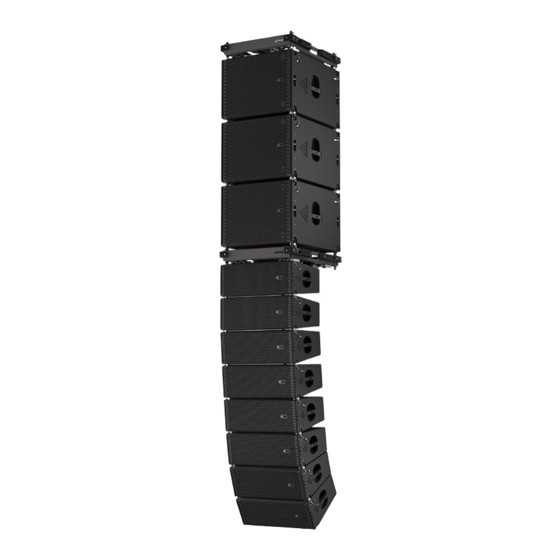
Page 9: Wasp Series
WASP-8 part number 00-0003869 A dual 8-inch system with a 1.5-inch throat HF WASP-S12 part number 00-0008340 driver, WASP has received the most advanced... -
Page 10: Specifications
4. Specifications WASP WASP-S12 WASP-S15 WASP-S18 Passive line array Arrayable passive Arrayable passive Arrayable passive System module subwoofer subwoofer subwoofer (discontinued) Frequency Response (−10dB) 70 - 20000 Hz 42 - 140 Hz 35 - 300 Hz 32 - 200 Hz Max SPL 141 dB (single cabinet) 140 dB... -
Page 11: System Operation
5. System operation 5.1. Rigging WASP line array comes with built-in mounting hardware for ground stack and flying cluster installation options. Rigging must be performed only by trained personnel following the established safety rules. MAXIMUM WEIGHT RESTRICTIONS MUST BE FOLLOWED AT ALL TIMES! MAKE SURE THE SUPPORT STRUCTURE IS CAPABLE OF HOLDING THE APPLIED WEIGHT WHILE SUSPENDING THE SYSTEM! -
Page 12: Connecting Two Wasp Modules
5.1.2. Connecting two WASP modules - Release two VA-0018 10 mm pins on the rear link and two VA-0010 8 mm pins on the front link. (Pic. 1) - Bring together two cabinets, then insert two VA 0010 8 mm pins into the front link from the sides of the cabinets. -
Page 13: Connecting A Flying Frame On The Top Of A Wasp Module
5.1.3. Connecting a flying frame on the top of a WASP module - Release two VA-0018 10 mm pins on the rear link and two VA-0010 8 mm pins on the front link. (Pic. 1) - Attach the WSF-02 or Bump-WASP-H flying frame on the top of the cabinet and insert two VA- 0010 pins in the front. -
Page 14: Connecting A Wsf-02 Or Bump-Wasp-H Frame On The Bottom Of A Wasp-8 Module
5.1.4. Connecting a WSF-02 or Bump-WASP-H frame on the bottom of a WASP-8 module - Release two VA-0018 10 mm pins on the rear link and two VA-0010 8 mm pins on the front link. (Pic. 1) - Place the cabinet on the top of the WSF-02 or Bump-WASP-H frame, and insert two VA-0010 8 mm pins into the front links. -
Page 15: Connecting A Wsf-02 Or Bump-Wasp-H Frame On The Top Of A Wasp-S12/S15/S18
5.1.5. Connecting a WSF-02 or Bump-WASP-H frame on the top of a WASP-S12/S15/S18 - Place the WFS-02 or Bump-WASP-H flying frame on the top of a WASP-S12/S15/S18, align so the front and rear links of a WASP-S12/S15/S18 fit into the receptacles of the frame (Pic. 1). - Insert four VA-0010 8 mm pins into the front and rear links of the WASP-S12/S15/S18. -
Page 16: Connecting Castor Wheels To The Wsf-02 Or Bump-Wasp-H Frame
Bump-WASP-H frame. The WSF-02 or Bump-WASP-H flying frame can fitted with four 100 mm castor wheels to easily transportation of WASP-8 or WASP-S12/S15/S18 subwoofer stacks. - To remove the castor wheel from the frame, press the lock on the frame, and pull the wheel to the center of the frame. -
Page 17: Extending The Tilt Angle On The Bump-Wasp-L
5.1.8. Extending the tilt angle on the Bump-WASP-L Bump-WASP-L supports a wide range of vertical tilt angles including negative (first array module looking down) and positive (first array module looking up). - Remove the safety pin and detach the upper mounting hole plank. -
Page 18: Connecting A Bump-Wasp-L Frame On The Top Of A Wasp-8
WASP-8 - Place the Bump-WASP-L flying frame on the top of a WASP-8, and align so the front and rear links of a WASP-8 fit into receptacles of the frame (1). - Release a pin holding the rear mounting hook of the Bump-WASP-L frame (2). -
Page 19: Building The Ground Stack Using The Bump-Wasp-L Frame
Bump-WASP-L frame. Use the winch to secure the Bump-WASP-L to the M20 socket of the subwoofer (3). - Position the WASP-8 module on top of the Bump- WASP-L frame. Remove two upper side pins of the Bump-WASP-L frame. Remove the rear holding pin of the WASP-8 module and release the rear link (4). -
Page 20: Using The Bump-Wasp-Ext15 Angle Extension
Bump-WASP-Ext15 (2). - Install the Bump-WASP-Ext15 onto the rear link of the WASP-8 module. Secure using the pin (3). - Tilt the WASP-8 module and install it’s rear link with connected Bump-WASP-Ext15 into the ground stack mounting hole of the mounting frame (4). -
Page 21: Installing The Mn Mounting Pli 01 Inclinometer
5.1.12. Installing the MN Mounting PLI 01 inclinometer Install the PLI 01 inclinometer onto the frame using 4 pcs of M4 counter-sunk screws. Refer to the PLI 01’s user manual for more detailed instructions on it’s usage. WASP Series User Manual rev 2.1... -
Page 22: Using Wsc-34 (Wsc-34A) Transportation Cart
5.1.13. Using WSC-34 (WSC-34A) transportation cart WSC-34 (WSC-34A) is a covered cart that can be used for convenient storage and easy transportation of WASP line array stacks. (Pic. 1) WASP-TB3 and WASP-TB4 transportation covers are available for 3 and 4-unit WASP stacks to be transported with WSC-34 (WSC-34A). - Page 23 - For 3 module WASP stacks, choose a 10° angle between cabinets. (Pic. 6) - For 4 module WASP stacks, choose a 10° angle between cabinets. (Pic. 7) - For storage of WSC-34 (WSC-34A), link the wooden cover with a steel cart using two VA-0010 pins.
-
Page 24: Connection
5.2. Connection 5.2.1. Connection plate and sticker plate 1. SERIAL NUMBER FIELD. The sticker with the system’s serial number is located here. NEVER REMOVE THE SERIAL FROM THE SYSTEM, AS IT IS AN IMMEDIATE WARRANTY VOID. 2. PARALLEL INPUTS. The pair of parallel Neutrik® Speakon connectors. -
Page 25: Standard Contents
WASP user manual Mounting pins Plastic bag Carton box VA-0010 8 mm pin - 4 pcs. WASP-8 VA-0018 10 mm pin - 2 pcs. WASP-S12 VA-0010 8 mm pin - 4 pcs. WASP-S15 VA-0010 8 mm pin - 4 pcs. -
Page 26: Accessories
7. Accessories WSF-02 Bump-WASP-H Versatile frame Versatile frame (discontinued) Part No. 00-0029677 Part No. 00-0029677 VA-0018 VA-0010 10 mm pin 8 mm pin Part No. 00-00002877 Part No. 00-00002878 WSC-34 Transportation cart Part No. 00-0008633 WSC-34A Transportation cart w/ auto wheels Part No. -
Page 27: Warranty And Assistance
8.2. Assistance 8.1. Product warranty There are no user-serviceable parts in your device. 1. By this warranty MAG Audio grants that all Refer servicing to qualified technical personnel. In equipment manufactured under the MAG Audio addition to the in-house service department, MAG... - Page 28 2 Merezhna str., Bila Tserkva, Kyiv region, 09100, Ukraine Tel./Fax.: +38 044 2774789 e-mail: info@mag-audio.com www.mag-audio.com...
Need help?
Do you have a question about the WASP-8 and is the answer not in the manual?
Questions and answers