
Related Manuals for MAG WASP Series


Summary of Contents for MAG WASP Series
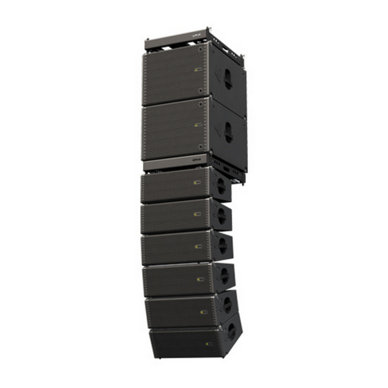
- Page 1 WASP User Manual Руководство пользователя Systems / Системы: WASP WASP-S12 WASP-S18 WASP Line Array User Manual rev 2.00...
-
Page 2: Table Of Contents
1. Safety instructions ...................................5 2. Regulatory information .................................6 3. WASP series ....................................7 3.1. Introduction ..................................7 3.2. WASP series speaker models ............................7 4. Specifications .................................... 8 5. System operation ..................................9 5.1. Rigging ....................................9 5.1.1. Connecting WASP modules to WASP-S12 or WASP-S18 subwoofers ...........9 5.1.2. - Page 3 WASP Line Array User Manual rev 2.00...
-
Page 4: Panel A. Dimensions
Panel A. Dimensions WASP WASP-S12 WASP-S18 WASP Line Array User Manual rev 2.00... -
Page 5: Safety Instructions
1. Safety instructions CAUTION RISK OF ELECTRIC SHOCK DO NOT OPEN EXPLANATIONS OF GRAPHICAL SYMBOLS IMPORTANT SAFETY INSTRUCTIONS The triangle with the lightning bolt is used to alert the 1. Read these instructions carefully. user to the risk of electric shock. 2. -
Page 6: Regulatory Information
EN 61000-4-6:2014 connected. EN 61000-4-11:2004 EN 60065:2002 /A1:2006 /A11:2008 /A2:2010 /A12:2011 - Consult the dealer or an experienced radio/TV technician for help. Bila Tserkva, 22 January 2019 Alexey Asanov For compliance questions: info@mag-audio.com WASP Line Array User Manual rev 2.00... -
Page 7: Wasp Series
3. WASP series 3.1. Introduction 3.2. WASP series speaker models WASP line array is a versatile array for any installation WASP user manual covers usage of following size, as small as restaurant or a bar, and as big as models: concert hall or a staduim. -
Page 8: Specifications
4. Specifications WASP-S12 WASP-S18 WASP System Arrayable passive sub- Arrayable passive sub- Passive line array module woofer woofer Frequency Response (−10dB) 70 - 20000 Hz 42 - 140 Hz 32 - 200 Hz Max SPL 141 dB (single cabinet) 140 dB 141 dB Sensitivity (1W/1m) 98 dB Low / 110 dB High... -
Page 9: System Operation
5. System operation 5.1. Rigging WASP line array comes with built-in mounting hardware for ground stack and flying cluster installation options. Rigging must be performed only by trained personnel following the established safety rules. MAXIMUM WEIGHT RESTRICTIONS MUST BE FOLLOWED AT ALL TIMES! MAKE SURE THE SUPPORT STRUCTURE IS CAPABLE OF HOLDING THE APPLIED WEIGHT WHILE SUSPENDING THE SYSTEM! -
Page 10: Connecting Two Wasp Modules
5.1.2. Connecting two WASP modules - Release two VA-0018 10 mm pins on the rear link and two VA-0010 8 mm pins on the front link. (Pic. 1) - Bring together two cabinets, then insert two VA-0010 8 mm pins into front link from the sides of the cabinets. -
Page 11: Connecting A Flying Frame On The Top Of A Wasp Module
5.1.3. Connecting a flying frame on the top of a WASP module - Release two VA-0018 10 mm pins on the rear link and two VA-0010 8 mm pins on the front link. (Pic. 1) - Attach WSF-02 flying frame on the top of the cabinet and insert two VA-0010 pins in the front. -
Page 12: Connecting A Flying Frame On The Bottom Of A Wasp Module
5.1.4. Connecting a flying frame on the bottom of a WASP module - Release two VA-0018 10 mm pins on the rear link and two VA-0010 8 mm pins on the front link. (Pic. 1) - Place the cabinet on the top of the WSF-02 frame, and insert two VA-0010 8 mm pin into the front links. -
Page 13: Connecting A Flying Frame On The Top Of A Wasp-S12 Or Wasp-S18
5.1.5. Connecting a flying frame on the top of a WASP-S12 or WASP-S18 - Place the WSF-02 flying frame on the top of a WASP-S12 (WASP-S18), align so front and rear links of a WASP-S12 (WASP-S18) fit into receptacles of the frame (Pic. -
Page 14: Connecting Castor Wheels To Wsf-02 Frame
5.1.7. Connecting castor wheels to WSF-02 frame WSF-02 flying frame can fitted with four 100 mm castor wheels to easily transportation of WASP, WASP-S12 or WASP-S18 stacks. - In order to remove the castor wheel from the frame, press the lock on the frame, and pull the wheel to the center of the frame. -
Page 15: Using Wsc-34 (Wsc-34A) Transportation Cart
5.1.8. Using WSC-34 (WSC-34A) transportation cart WSC-34 (WSC-34A) is a covered cart that can be used for convenient storage and easy transportation of WASP line array stacks. (Pic. 1) WASP-TB3 and WASP-TB4 transportation covers are available for 3 and 4 unit WASP stacks to be transported with WSC-34 (WSC-34A). - Page 16 - For 3 module WASP stacks, choose 10° angle between cabinets. (Pic. 6) - For 4 module WASP stacks, choose 10° angle between cabinets. (Pic. 7) - For storage of WSC-34 (WSC-34A), link wooden cover with steel cart using two VA-0010 pins. (Pic. - For compact storage, WSC-34 (WSC-34A) can be stacked on one another using sockets for castor wheels for positioning.
-
Page 17: Passive Speakers
Speakon connectors. Use this connectors to connect power amplifier and to feed the signal to the parallel systems. 1+1- LO 16 Ohm 2+ 2- HI 16 Ohm Made in Ukraine www.mag-audio.com WASP connection plate 5.2.2. Passive connections Suggested accessories: WASP module CN-0021 (part No. 00-00004268) CN-0031 (part No. -
Page 18: Standard Contents
6. Standard contents Please check complete complement of your WASP system upon receiving the package. Standard contents of a WASP line array module: System WASP user manual Mounting pins Plastic bag Carton box VA-0010 8 mm pin - 4 pcs. WASP VA-0018 10 mm pin - 2 pcs. -
Page 19: Warranty And Assistance
8. Warranty and assistance 8.2. Assistance 8.1. Product warranty There are no user-serviceable parts in your 1. By this warranty MAG Audio grants that all device. Refer servicing to qualified technical equipment manufactured under the MAG Audio personnel. addition in-house... - Page 20 2 Merezhna str., Bila Tserkva, Kyiv region, 09100, Ukraine Tel./Fax.: +38 044 2774789 e-mail: info@mag-audio.com www.mag-audio.com WASP Line Array User Manual rev 2.00...
Need help?
Do you have a question about the WASP Series and is the answer not in the manual?
Questions and answers