
Related Manuals for Meinberg LANTIME M320/GPS


Summary of Contents for Meinberg LANTIME M320/GPS
- Page 1 TECHNICAL REFERENCE LANTIME M320/GPS February 1, 2023 Meinberg Funkuhren GmbH & Co. KG...
-
Page 3: Table Of Contents
Table of Contents 1 Imprint 2 Copyright and Liability Exclusion 3 Presentation Conventions in this Manual Conventions for the Presentation of Critical Safety Warnings ..... Secondary Symbols Used in Safety Warnings . - Page 4 12.4 Technical Specifications: Antenna Cable ....... . . 12.5 How Satellite Navigation Works ........12.5.1 Time Zones and Daylight Saving Time .
-
Page 5: Imprint
1 Imprint 1 Imprint Meinberg Funkuhren GmbH & Co. KG Lange Wand 9, 31812 Bad Pyrmont, Germany Phone: + 49 (0) 52 81 / 93 09 - 0 Fax: + 49 (0) 52 81 / 93 09 - 230 Website: https://www.meinbergglobal.com Email: info@meinberg.de... -
Page 6: Copyright And Liability Exclusion
Meinberg reserves the right to make changes of any type to this document at any time as is necessary for the purpose of improving its products and services and ensuring compliance with applicable standards, laws &... -
Page 7: Presentation Conventions In This Manual
3 Presentation Conventions in this Manual 3 Presentation Conventions in this Manual 3.1 Conventions for the Presentation of Critical Safety Warnings Warnings are indicated with the following warning boxes, using the following signal words, colors, and symbols: Caution! This signal word indicates a hazard with a low risk level. Such a notice refers to a procedure or other action that may result in minor injury if not observed or if improperly performed. -
Page 8: Conventions For The Presentation Of Other Important Information
3.3 Conventions for the Presentation of Other Important Information Beyond the above safety-related warning boxes, the following warning and information boxes are also used to indicate risks of product damage, data loss, and information security breaches, and also to provide general information for the sake of clarity, convenience, and optimum operation: Important! Warnings of risks of product damage, data loss, and also information security risks are indicated with... -
Page 9: Important Safety Information
Depending on your specific device configuration and installed options, some safety information may not be applicable to your device. Meinberg accepts no responsibility for injury or death arising from a failure to observe the safety information, warnings, and safety-critical instructions provided in the product documentation. -
Page 10: Product Documentation
Read the product manual carefully and completely before you set the product up for use. Safety standards and regulations change on a regular basis and Meinberg updates the corresponding safety information and warnings to reflect these changes. It is therefore recommended to visit the Meinberg website at https://www.meinbergglobal.com regularly to download up-to-date manuals. -
Page 11: Safety When Installing The Device
Never drill holes into the device to mount it! If you are experiencing difficulties with rack installation, contact Meinberg’s Technical Support team for assistance! Inspect the device housing before installation. The device housing must be free of any damage when it is installed. -
Page 12: Electrical Safety
Custom cables may only be assembled by a qualified electrician. This Meinberg product uses hot-pluggable power supply modules that can be replaced while the system is in operation. When removing a hot-pluggable power supply module, the power cable plug must always... - Page 13 4 Important Safety Information 5-Pin MSTB Connector 3-Pin MSTB Connector = 100 - 200 V = 90 - 250 V Fig.: Lock screws on an MSTB plug connector; in this case on a LANTIME M320 Ensure that all plug connections are secure. In particular, when using plug connectors with lock screws, ensure that the lock screws are securely tightened.
-
Page 14: Special Information For Devices With Ac Power Supply
4.4.1 Special Information for Devices with AC Power Supply This device is a Protection Class 1 device and may only be connected to a grounded outlet (TN system). For safe operation, the installation must be protected by a fuse rated for currents not exceeding 16 A and equipped with a residual-current circuit breaker in accordance with applicable national standards. -
Page 15: Safety When Maintaining And Cleaning The Device
If a power supply unit or module is no longer functional (for example due to a defect), it can be returned to Meinberg for repair. Some components of the device may become very hot during operation. Do not touch these surfaces! If maintenance work is to be performed on the device and the device housing is still hot, switch off... -
Page 16: Important Product Information
5 Important Product Information 5.1 CE Marking This product bears the CE mark as is required to introduce the product into the EU Single Market. The use of this mark is a declaration that the product is compliant with all re- quirements of the EU directives effective and applicable as at the time of manufacture of the product. -
Page 17: Maintenance And Modifications
• Some configuration options relating to the reference clock are lost every time the system is restarted. In this case you should not replace the battery on your own. Please contact the Meinberg Technical Support team, you will provide you with precise guidance on how to perform the replacement. -
Page 18: Prevention Of Esd Damage
5.5 Prevention of ESD Damage An ESDS device (electrostatic discharge-sensitive device) is any device at risk of dam- age or malfunction due to electrostatic discharge (ESD) and thus requires special mea- sures to prevent such damage or malfunction. Systems and modules with ESDS devices usually bear this symbol. -
Page 19: Disposal
It can be returned to Meinberg for disposal. In this case, the shipping costs are to be borne by the customer, while Meinberg will cover the costs for disposal. If you wish for Meinberg to handle disposal for you, please get in touch with us. - Page 20 Disposal of Packaging Materials The packaging materials that we use are fully recyclable: Material Use for Disposal ———————————————————————————————————————— Polystyrol packaging frame/filling material Recycling Depot (polystyrene peanuts, bubble wrap) PE-LD accessories packaging Recycling Depot Polyethylene low density Cardboard shipping packaging, Paper recycling accessories packaging ————————————————————————————————————————...
-
Page 21: Introduction To Your Lantime Server
Thank you for purchasing your new LANTIME time server. Meinberg’s LANTIME Series M servers rely on proven, robust, and resilient technology to provide an ab- solute and highly precise NTP time reference in a variety of chassis types, whether for rack installation, DIN rail mounting, or desktop use. -
Page 22: Installation Of The Gps Or Gnss Antenna
7 Installation of the GPS or GNSS Antenna Danger! Do not mount the antenna without an effective fall arrester! Danger of death from falling! • Ensure that you work safely when installing antennas! • Never work without an effective fall arrester! Danger! Do not work on the antenna system during thunderstorms! Danger of death from electric shock! - Page 23 Case Example 4: If the cable leading from the point of entry into the building to the Meinberg system is laid together with other cables (for example in a cable duct alongside high-voltage cables), transient voltages may "leak" into the antenna cable, causing damage to your system.
- Page 24 Type-N (Male) If installed in a waterproof enclosure, the MBG S- Type-N (Female) PRO can be installed outdoors. However, Meinberg recommends installing the surge protector indoors—as closely to the entrance point of the antenna cable as possible—in order to minimize the risk of surge dam- age (such as that caused by lightning strike).
- Page 25 7 Installation of the GPS or GNSS Antenna Grounding Conductor To ground the antenna cable, connect the surge protec- to Grounding Busbar tor to a grounding busbar using a grounding conductor Conductor of diameter approx. 1.5 mm (see illustration). attached to surge protector As short as possible Once installation is complete, connect the other end of the antenna cable to the surge protector female con-...
- Page 26 The splitter may be installed at any location between the surge protector and the receivers. Information: Please note for installation purposes that GNSS L1 components cannot be directly connected to or used with a Meinberg GPS antenna distributor. Antenna Receiver Antenna Splitter...
-
Page 27: Antenna Short Circuit
7 Installation of the GPS or GNSS Antenna 7.1 Antenna Short Circuit Information: This information only applies to devices with a front display. If the antenna line is short-circuited, the following message will be shown on the display: Antenna Short -Circuit Disconnect Power!!! If this message appears, the LANTIME system must be switched off... -
Page 28: Connecting Your Lantime System
8 Connecting Your LANTIME System Important! • Please ensure that you have read and understood the safety information at the start of this manual before you connect your LANTIME system, and that you perform the procedure in the order listed here. •... - Page 29 8 Connecting Your LANTIME System Assuming that your power source(s) are active, the green "Power" LED(s) for the relevant power supply mod- ule(s) should light up and the front panel display should show "Starting up ...please wait", before it indicates the progress of its startup process. LANTIME Date: February 1, 2023...
-
Page 30: Configuring Your Lantime System For Your Network
9 Configuring your LANTIME System for Your Network IPv4 Network Configuration Press the F2 button twice on the front panel to open the setup menu of your LANTIME system. Press the OK button to select "Interfaces". You will be prompted to select the network interface. Select the appropriate interface and press OK to confirm. - Page 31 9 Configuring your LANTIME System for Your Network IPv6 Network Configuration Press the F2 button twice on the front panel to open the setup menu of your LANTIME system. Press the OK button to select "Interfaces". You will be prompted to select the network interface. Select the appropriate interface and press OK to confirm.
-
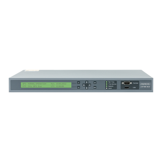
Page 32: Lantime M320 Front Panel
10 LANTIME M320 Front Panel GPS: NORMAL OPERATION MON, dd.mm.yyyy NTP: Offset: PPS -5us UTC: 12:00:00 The main menu is displayed after the device has booted. The main menu provides the most impor- tant status information at a glance. The top line of the display shows the operating mode of the reference clock / reference time and will normally read "GNSS: NORMAL OPERATION". - Page 33 10 LANTIME M320 Front Panel The four arrow buttons and the "OK", "ESC", "F1", and "F2" buttons on the keypad can be used to navigate through each menu in the display. The "ESC" button returns you to the previous menu; you can return to the main menu accordingly by pressing the "ESC"...
- Page 34 All M-series LANTIME devices have a USB interface that allow a USB storage medium such as a flash drive to be connected. USB storage media can be used for the following tasks: • locking the keys on the LC display to prevent unauthorized access •...
-
Page 35: Lantime M320 Rear Connectors
11 LANTIME M320 Rear Connectors 11 LANTIME M320 Rear Connectors Information: The numbering above relates to the corresponding subsection in this chapter. The drawing shows the inputs, outputs and power supply as well as the configuration options of a LAN- TIME M320/GPS/(LNE)/AD10(-DC20). -
Page 36: Ac/Dc Power Supply Connection
11.1 AC/DC Power Supply Connection AC/DC Power Supply Danger! This equipment is operated at a hazardous voltage. Danger of death from electric shock! • This device must be connected by skill personnel or instructed personnel only. • Never handle exposed terminals or plugs while the power is on. •... - Page 37 11 LANTIME M320 Rear Connectors DC Power Supply Technical Specifications Connector Type: 5-Pin MSTB Pin Assignment: 1: Not Connected 2: V DC20 3: PE (Protective Earth) 4: V Power 5: Not Connected Power Supply Specifications 24 V - 48 V = 20 V - 60 V ————————————————————————————...
- Page 38 Cut off the power supply to the module by pulling the mains plug of the power supply cable out of the mains socket. Remove the 5-pin MSTB plug from the power supply unit after loosening the two screws (B) using the slotted screwdriver.
-
Page 39: Comx Time String: Rs-232
11 LANTIME M320 Rear Connectors 11.2 COMx Time String: RS-232 Data Transfer: Serial Baud Rate/Framing: 19200 / 8N1 (Default) Time String: Meinberg Standard (Default) Assignment: Pin 2: TxD (Transmit) Pin 3: RxD (Receive) Pin 5: GND (Ground) COM x Connection Type:... -
Page 40: Error Relay
11.3 Error Relay The device is equipped with a 3-pin relay output la- beled with "Error". This 0 V ("dry") relay output is connected to the TTL TIME_SYNC output of the refer- Error ence clock (GPS, PZF, TCR, etc.) Normally, when the internal reference clock has been synchronized to its source (GPS, DCF77, or IGIG), this relay will switch to "NO"... -
Page 41: Antenna Input: Gps Reference Clock
11 LANTIME M320 Rear Connectors 11.4 Antenna Input: GPS Reference Clock Antenna Input Antenna Circuit, Galvanically Isolated Dielectric Strength: 1000 V N-Norm Type-N Receiver Type: 12-Channel GPS Receiver Signal Support: L1 C/A (1575.42 MHz) Antenna Antenna Mixing Frequency GNSS | IF | 15 V GNSS | IF | 15 V Reference Clock to Antenna (GPS Converter):... -
Page 42: Pulse Per Second Output
11.5 Pulse per Second Output Output Signal: PPS (Pulse per Second) Signal Level: TTL = 5 V (without load), 2.5 V (with 50 load) Rise Time: typ. 4 ns Fall Time: typ. 4 ns PPS Out Pulse Length: 200 ms Connector Type: BNC Female Cable:... -
Page 43: Technical Appendix
12 Technical Appendix 12 Technical Appendix 12.1 Technical Specifications: LANTIME Chassis Chassis Type: 19" Multipac Chassis, 1U Chassis Material: Sheet Steel ——————————————————————————- Power Consumption: Standard Configuration: Max. 20 W (Max. 50 W dependent on additional I/O options) ——————————————————————————- Temperature Range Ambient Temperature: 0 C to 50 C (32 F to 122 F) - Page 44 Chassis Dimensions 483 mm 19 inch 465 mm 18.31 inch 43,6 mm 1.72 inch 31,8 mm 1.25 inch 445 mm 17.51 inch 288 mm 11.32 inch 304 mm 11.98 inch External Ground Conductor Terminal on Chassis Information: For information on how to mount the earth cable, see chapter Connecting Your LANTIME System Date: February 1, 2023 LANTIME...
-
Page 45: Technical Specifications: Gps Antenna And Accessories
12 Technical Appendix 12.2 Technical Specifications: GPS Antenna and Accessories Physical Dimensions: LANTIME Date: February 1, 2023... - Page 46 Specifications: Power Supply: 15 V, 100 mA (provided via antenna cable) Reception Frequency: 1575.42 MHz Bandwidth: 9 MHz Frequencies: Mixed Frequency 10 MHz IF frequency: 35.4 MHz Connector: Type-N Female Form Factor: ABS Plastic Case for Outdoor Installation IP Rating: IP66 Humidity: 95 %...
-
Page 47: Technical Specifications: Mbg S-Pro Surge Protector
12 Technical Appendix 12.3 Technical Specifications: MBG S-PRO Surge Protector Adapter plug with replaceable gas discharge tube for coaxial signal connections. Connector Type: Type-N connector female/female. The MBG S-PRO set includes a surge protector (Phoenix CN-UB-280DC-BB), a pre-assembled coaxial cable, and a mounting bracket. The coaxial cable surge protector must be installed on the antenna line. - Page 48 Max. Discharge Current: (8/20) s Maximum (Core-Shield) 20 kA Rated Pulse Current: (10/1000) s (Core-Shield) 100 A Impulse Discharge Current: (10/350) s, Peak Value I 2.5 kA Output Voltage Limit: At 1 kV/ s (Core-Earth) spike 900 V At 1 kV/ s (Core-Earth) spike 900 V Response Time: tA (Core-Earth)
-
Page 49: Mbg S-Pro: Physical Dimensions
12.4 Technical Specifications: Antenna Cable The table below shows which coaxial cable types and lengths are supported by Meinberg for each of the receiver types. If you need to purchase a replacement cable at any time, please refer to this table to ensure that you select cable with suitable cutoff... - Page 50 12.5 How Satellite Navigation Works The use of a receiver for location tracking and time synchronization relies on the ability to measure the satellite- to-receiver propagation delay as precisely as possible. It is necessary to have simultaneous reception from four satellites so that the receiver can determine its relative spatial position in three dimensions (x, y, z) and mea- sure the deviation of its clock against the system clock.
- Page 51 13 RoHS Conformity 13 RoHS Conformity Conformity with EU Directive 2011/65/EU (RoHS) We hereby declare that this product is compliant with the European Union Directive 2011/65/EU and its delegated directive 2015/863/EU “Restrictions of Haz- ardous Substances in Electrical and Electronic Equip- ment”.
- Page 52 14 Declaration of Conformity for Operation in the European Union EU-Konformitätserklärung Doc ID: LANTIME M320/GPS-November 30, 2022 Hersteller Meinberg Funkuhren GmbH & Co. KG Manufacturer Lange Wand 9, D-31812 Bad Pyrmont erklärt in alleiniger Verantwortung, dass das Produkt, declares under its sole responsibility, that the product...
- Page 53 14 Declaration of Conformity for Operation in the European Union EU-Declaration of Conformity Doc ID: LANTIME M320/GPS-November 30, 2022 Diese EU-Konformitätserklärung umfasst alle nachfolgend aufgeführten Gerätekonfigurationen: This UKCA Declaration of Conformity further covers all the device configurations listed below: LANTIME...
- Page 54 15 Declaration of Conformity for Operation in the United Kingdom UKCA Declaration of Conformity Doc ID: LANTIME M320/GPS-November 30, 2022 Manufacturer Meinberg Funkuhren GmbH & Co. KG Lange Wand 9 31812 Bad Pyrmont Germany declares that the product Product Designation...
- Page 55 15 Declaration of Conformity for Operation in the United Kingdom UKCA Declaration of Conformity Doc ID: LANTIME M320/GPS-November 30, 2022 This UKCA Declaration of Conformity further covers all the device configurations listed below: LANTIME M320/GPS/AD10 M320/GPS/AD10-AD10 M320/GPS/AD10-DC20 M320/GPS/DC20 M320/GPS/DC20-DC20 M320/GPS/LNE/AD10...
Need help?
Do you have a question about the LANTIME M320/GPS and is the answer not in the manual?
Questions and answers