Table of Contents
Advertisement
Quick Links
- 1 Troubleshooting
- 2 Bt-Ckb5Efi Parts Reference (Serial # 24186-25614)
- 3 Bt-Ckb5Efi Parts Reference (Serial # 27921-31740)
- 4 Bt-Ckb5Efi Parts Sub-Assemblies
- 5 Bt-Ckb5Efi Wireless Remote System Manual
- 6 Wireless System Transmitter Programming
- 7 Wiring Schematic for Wireless Remote System
- 8 Wireless System Troubleshooting Guide
- Download this manual
Advertisement
Table of Contents
Troubleshooting

Related Manuals for BUFFALO TURBINE BT-CKB5EFI


Summary of Contents for BUFFALO TURBINE BT-CKB5EFI
- Page 1 BUFFALO TURBINE 180 Zoar Valley Road Springville, NY 14141 TEL: 716 592 2700 FAX: 716 592 2460 EMAIL: info@buffaloturbine.com WEBSITE: www.buffaloturbine.com BUFFALO TURBINE'S BT-CKB5EFI ORIGINAL INSTRUCTIONS AND PARTS MANUAL 12/19 -BT MAN...
-
Page 2: Table Of Contents
Moreflex Coupling Installation BT-CKB5EFI Parts Reference (Serial # 24186-25614) BT-CKB5EFI Parts Reference (Serial # 25614-27920) BT-CKB5EFI Parts Reference (Serial # 27921-31740) BT-CKB5EFI Parts Reference (After Serial # 31741) BT-CKB5EFI Parts Sub-Assemblies Bill of Materials for BT-CKB5EFI BT-CKB5EFI Wireless Remote System Manual... -
Page 3: Introduction
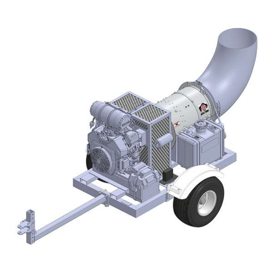
This Manual covers the BT-CKB5EFI Turbine Blower. Keep this manual handy for frequent reference and to pass on to new operators or owners. Call your Buffalo Turbine dealer or distributor if you need assistance, information, or additional copies of the manuals. -
Page 4: Safety
YOU are responsible for the SAFE operation and maintenance of your Buffalo Turbine Debris Blower. YOU must ensure that you and anyone else, who is going to operate, maintain or work around the Buffalo Turbine Blower be familiar with the operating and maintenance procedures and related SAFETY information contained in this manual. -
Page 5: Safety Decals
SAFETY DECALS The types of decals on the blower unit are shown below. Good safety requires that you familiarize yourself with the various Safety Decals, the type of warning and the area, or particular function related to that area that requires your SAFETY AWARENESS.* THINK SAFETY! WORK SAFELY! !ATTENTION! KEEP HANDS, FEET AND CLOTHING AWAY FROM POWER DRIVEN PARTS. -
Page 6: Transport Safety
Cover with a weatherproof tarpaulin and tie down securely. SIGN-OFF FORM Buffalo Turbine recommends that anyone who will be operating and/or maintaining the Buffalo Turbine Blower must read and clearly understand ALL Safety, Operating and Maintenance information presented in this manual. ... -
Page 7: Warranty Information
Obligation under this warranty shall extend for a period of 10 years from date of purchase and, at the option of Buffalo Turbine, replacement of any parts found, upon inspection by Buffalo Turbine, to be defective. -
Page 8: 3.1 Warranty Registration Form
WARRANTY REGISTRATION FORM & INSPECTION REPORT Any units not registered with Buffalo Turbine are not eligible for warranty claims This form must be filled out by the dealer and signed by both the dealer and the customer at the time of delivery Dealer’s Name... -
Page 9: Operations
TO THE NEW OPERATOR OR OWNER Buffalo Turbine Debris Blowers are designed to quickly and efficiently, blow away leaves, cuttings and other debris. The material is conveyed on a stream of high volume and velocity of air to remove it from the area of concern. When the material is removed, it gives a neat, professional look to the working area. -
Page 10: Model Bt-Ckb5Efi Assembly Instructions
MODEL BT-CKB5EFI Assembly Instructions Fill engine oil to proper level. (overseas shipments) Fill each cell to proper level (Dry Cell Battery) with battery-grade sulfuric acid of 1.265 specific gravity. Battery and acid must be at a temperature of 60F to 100F (16C to 38C) at the time of filling (overseas shipments). -
Page 11: Field Operation
Do not allow children to play around the stored unit. TROUBLE SHOOTING The Buffalo Turbine Debris Blower uses a high volume and velocity of air to move material from one place to another. The system is simple and reliable requiring minimal maintenance. -
Page 12: Machine Specification
Machine Specifications Model CKB5EFI Series Frame Size 28” wide X 48” Long Length: 102” With nozzle 82” Without nozzle 69” With nozzle installed but Without trailer arm 48” Without nozzle and trailer arm installed Width: 48” With axle and tires 38.5”... -
Page 13: Maintenance
MAINTENANCE SECTION Maintenance Safety Set Blower on a level surface, stop engine, set park brake, remove ignition key and wait for all moving parts to stop before dismounting to service, adjust or repair. Reinstall and secure all guards removed for servicing before starting to use machine again. *We recommend wearing gloves when removing or installing the guard to avoid getting cut* Securely support machine with blocks or safety stands when changing tires or working beneath it. -
Page 14: Moreflex Coupling Parts
INSTALLATION INSTRUCTIONS & PARTS FOR THE MOREFLEX COUPLING PART # 1746 – COUPLING COMPLETE, KOHLER ENGINE Includes PN 1110(1pc), 1111(1pc), 1112(4pc), 1113(4pc), 1114(1pc), 1115(1pc), 1256(1pc), 2869(4pc) ALIGNMENT OF TURBINE SHAFT WITH SHAFT OF ENGINE IS CRITICAL Install keys in both shafts. Slide coupling flanges on both shafts (engine and turbine shafts) Place Moreflex coupling CENTER SECTION between coupling flanges and secure with 4 bolts and TOPLOC nuts. -
Page 15: Moreflex Coupling Installation
MOUNTING BLOWER ASSEMBLY ONTO FRAME AND ALIGNMENT RECOMMENDATIONS Install blower assembly onto frame and tighten all of the bolts. Remove all burrs and oil from the shafts and keyways (engine and blower shafts). Using the supplied gauge, align the shafts parallel to each other (very important). Check in four places around the shafts at 90... -
Page 21: Bill Of Materials For Bt-Ckb5Efi
BILL OF MATERIALS FOR BT-CKB5EFI REF PAGE # DESCRIPTION 1100 3/8-24 X 1-1/4 HHCS ZINC GR 5 1101 3/8-24 X 1-1/2 HHCS ZINC GRADE 5 1102 3/8-24 X 1-3/4 HHCS ZINC 1104 3/8-24 X 2 HHCS ZINC GRADE 5 1105... -
Page 22: Bt-Ckb5Efi Wireless Remote System Manual
BUFFALO TURBINE WIRELESS REMOTE SYSTEM MANUAL FOR BT-CKB5EFI Specifications: Receiver (BT PN 3585) WIRELESS RECEIVER Transmitter (BT PN 3586) WIRELESS TRANSMITTER 6 BUTTON, EFI Supply Voltage: 12VDC IP Class: IP65 System Description: This machine is set to run at Idle Speed = 1250 RPM, Normal High Throttle = 3600RPM (Note: Holding “THROTTLE UP”... -
Page 23: Wireless System Transmitter Programming
This procedure should be used to pair a single transmitter to the receiver. If you need multiple transmitters paired to this Receiver contact Buffalo Turbine at 716-592-2700 for assistance. If a valid code from an already registered TX is received, the receiver will go directly into normal operating mode. This is to speed up the startup time. -
Page 24: Wireless System Warranty Information
GUARANTEE, SERVICE, REPAIRS AND MAINTENANCE FOR WIRELESS SYSTEM Buffalo Turbine products are covered by a guarantee against material, construction and manufacturing faults. During the guarantee period, Buffalo Turbine may replace the product or faulty parts. Work under guarantee must be authorized by Buffalo Turbine. -
Page 25: Wireless Remote System Diagnostic Tests
Troubleshooting For Cyclone KB5EFI Remote / Receiver CONTACT BUFFALO TURBINE AT 716-592-2700 FOR ASSISTANCE WITH TROUBLESHOOTING Troubleshooting the RF control system should begin by considering the problem(s) exhibited and verifying the basics of the system. Keep in mind that many of the problems can be caused by actuator, controller, or engine problems. Refer to the section “Controller and Actuator Measurements” for details on recommended methods of taking some useful measurements. - Page 26 No High Speed – speed does not change when commanded Engine is controlled at low governed speed. Changes to the load at low speed result in the engine speed recovering to the set speed after the load change. Potential causes: Missing high speed select signal Mechanical travel limited Engine Overloaded...
-
Page 27: Wiring Schematic For Wireless Remote System
Specifications Actuator Coil resistance: 12v: 3.2 +/- 5% at 68 deg F Coil resistance to housing: open circuit. Note that human contact with either or both DMM leads and the housing may cause resistance of >10k to be measured. Table 1: Controller Connections Refer to system schematic for controller functionality. - Page 28 Figure 1: Wiring Schematic...
-
Page 29: Wireless System Troubleshooting Guide
Symptom Items to Check Possible Remedy Key Switch not turned to Run Position Turn on Key Switch Charge low in batteries in hand held Change batteries in remote remote. Check that when Run button is pushed Red LED on remote illuminates. With key on check that engine warning Replace blown fuse.
Need help?
Do you have a question about the BT-CKB5EFI and is the answer not in the manual?
Questions and answers