Table of Contents
Advertisement
Quick Links
Advertisement
Table of Contents

Subscribe to Our Youtube Channel
Related Manuals for CIM PRO THERMAL 2000


Summary of Contents for CIM PRO THERMAL 2000
- Page 1 THERMAL 2000 PRO SERIES ...
- Page 2 MF GROUP, Srl. CIM Via Serra, 2 - Calderara di Reno 40012 BOLOGNA - Italy Tel +39 051 6465011 Fax +39 051 6465012 www.cimitaly.it ...
-
Page 3: Table Of Contents
TABLE OF CONTENTS 0 INTRODUCTION 1.1 USE OF THIS MANUAL ....................0 1.1.1 Importance of this manual .................. 0 1.1.2 Keeping the manual ................... 0 1.1.3 Consulting the manual ..................0 1.1.4 Symbols used ..................... 0 1.1.5 Updating the manual with the machine modifications ......... 0 1.1.6 Original srlre parts .................... - Page 4 TABLE OF CONTENTS 2 UNPACKING 2.1 UNPACKING ........................2 - 3 3 INSTALLATION 3.1 ACCESSORIES SUPPLIED ....................3 - 3 3.2 OPTIONAL ACCESSORIES ..................... 3 - 4 3.3 ELECTRICAL CONNECTIONS T2000 ................3 - 5 3.4 PC CONNECTIONS ......................3 - 5 3.5 ADVISE AND CARE FOR A CORRECT INSTALLATION ..........
- Page 5 TABLE OF CONTENTS 5.2 LOADING UNIT ADJUSTMENT ..................5 5.3 LOADING TOOTH REPLACEMENT ................5 5.4 MANUAL COMMAND KEYPAD..................5 5.4.1 Leds ........................5 5.4.2 Buttons ......................... 5 5.5 REPLACING THE CLEANING TAPE ................5 5.6 REPLACING THE PRINTING RIBBON ................5 6 TROUBLESHOOTING 6.1 PROBLEMS AND SOLUTIONS ..................
- Page 6 TABLE OF CONTENTS A.11 KEYPAD LCD ............A - 19 A.12 THERMOGRAFIC SETUP .
-
Page 7: Introduction
0 INTRODUCTION PRO SERIES 0 - 1 OPERATOR’S MANUAL PRO SERIES... - Page 8 0 INTRODUCTION This page is intentionally left blank 0 - 2 ...
-
Page 9: Use Of This Manual
1,2 and 3, as the effectiveness of any servicing operations depends on the correct and methodical application of the information contained herein. If you run into difficulties or setbacks, CIM SERVICE DEPARTMENT will be happy to provide you with the necessary advice and assistance. -
Page 10: Symbols Used
0 INTRODUCTION 1.1.4 Symbols used The Safety symbols and notices shown below are used throughout this manual to draw the reader’s attention to the hazards associated with particular procedures and operations which could result in damage to the machines or personal injury, or to indicate good working practices. - Page 11 0 INTRODUCTION ATTENTION! MOVING MACHINE COMPONENTS Prohibition notices (circular) denoting operations which are expressly prohibited to avoid risk of personal injury. THE OPERATION INDICATED IN THE TEXT IS STRICTLY PROHIBITED ...
-
Page 12: Updating The Manual With The Machine Modifications
0 INTRODUCTION 1.1.5 Updating the manual with the machine modifications If the MACHINE or MANUAL are MODIFIED in any way, an UPDATE will be sent to be integrated in the Manual. 1.1.6 Original srlre parts To help us provide a fast and efficient service, always specify the following information when ordering replacement parts: •... -
Page 13: General Description
1 GENERAL DESCRIPTION PRO SERIES 1 - 1 OPERATOR’S MANUAL PRO SERIES... - Page 14 1 GENERAL DESCRIPTION This page is intentionally left blank 1 - 2 ...
-
Page 15: Production Cycle
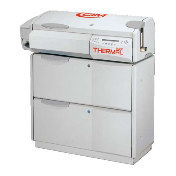
The T2000 PRO machine works connected to a PC which sends the personalization data using the serial CIM protocol CHIP 10. The machine is equipped with an upper cover (2) with locking key, a push-to-open discharge unit (1) and front panel (3). -
Page 16: Loading And Encoding Unit
1 GENERAL DESCRIPTION 1.3 LOADING AND ENCODING UNIT The loading unit (1) allows to store vertically 200 cards 0,76 mm thick. The card at the bottom of the pile is picked up and moved to the working units. The bar code encoding function can be integrated in the unit, in accordance with the standards ISO and JIS (Japan). -
Page 17: Cleaning Unit
(overlay). The printing is obtained by overlapping in 5 passages. ATTENTION! THE PRINTING HEAD IS A CUSTOM CIM UNIT. ONLY USE ORIGINAL HEADS. IF YOU USE HEADS WHICH ARE NOT ORIGINAL YOU MAY DAMAGE THE MODULE LOGIC CARDS EVEN THOUGH THE HEADS MIGHT BE SIMILAR. -
Page 18: Unloading Unit
1 GENERAL DESCRIPTION 1.7 UNLOADING UNIT The unloading unit (3), with removable cover (1), allows to extract the cards. The cards successfully produced are stored in the upper part (2) of the unit, while the defective ones are placed in the lower part (4). -
Page 19: Electrical And Technical Specifications
1 GENERAL DESCRIPTION 1.8 ELECTRICAL AND TECHNICAL SPECIFICATIONS Power Supply 230 V 50 Hz or 117V 60Hz Absorbed Power 200 W Current rating 2 A nom (230 V) 2,5 A nom (117 V) Fuses (2) 5x20 mm T 2,5 A 250 V (230 V) T 4 A 250 V (117 V) Logic... -
Page 20: Equipment Classification And Standard Reference
1 GENERAL DESCRIPTION 1.9 EQUIPMENT CLASSIFICATION AND STANDARD REFERENCE Category IP Protection IP 20 Standard reference IEC EN 50081-1 IEC EN 50082-1 IEC EN 60950 4th issue 1.10 PHYSICAL ENVIRONMENT AND OPERATING CONDITIONS ... -
Page 21: Production Capacity
1 GENERAL DESCRIPTION 1.12 PRODUCTION CAPACITY ATTENTION! THE MACHINE IS NOT INTENDED FOR CONTINUOUS USE (MAX. 8-9 HOURS/DAY). Card dimensions Standard ISO CR80 Card thickness from 0,40 mm to 0,84 mm (ISO 7810 = 0,76) Thermographic printing full card area (300 dpi) Thermographic ribbon... -
Page 22: Positioning The Machine
1 GENERAL DESCRIPTION 1.13 POSITIONING THE MACHINE The machine should work in a closed room protected from dust and excessive humidity. The machine should be positioned in such a way that its distance from the walls, doors, windows, other machines or working positions guarantees immediate access in the case of urgency, maintenance or reparation. -
Page 23: General Safeties
1 GENERAL DESCRIPTION 1.14 GENERAL SAFETIES This machine complies with all the safety requirements of the main European and extra-European Standards. However we would recommend to read carefully the following pages. These instructions recall the warning symbols used in the Operator Area of the machine and show any possible dangerous situation with the precaution that you have to adopt. - Page 24 DISCONNECTED. Do not remove or modify in any circumstances the enclosures and the internal protections. In case of necessity refer to the CIM Technical Service. MF GROUP Srl. cannot be held responsible for the consequences of not complying with these rules when using the machine.
-
Page 25: Residual Risks And Dangerous Areas
The machine can work with the safety guards deactivated. This mode allows to operate the machine with the safety covers open. Contact CIM Technical Service to receive the service keys and the abilitation to use the machine in the service mode. -
Page 26: Safety Guards Functional Check
1 GENERAL DESCRIPTION 1.17 SAFETY GUARDS FUNCTIONAL CHECK To ensure safe machine operations, the safety guards mounted on the machine covers must function correctly. Before starting production (at least once a day), turn on the machine; when it is in the READY mode, open the upper cover. -
Page 27: Declaration Of Conformity
1 GENERAL DESCRIPTION 1.18 DECLARATION OF CONFORMITY DECLARATION OF ‘CE’ CONFORMITY The manufacturer MF Group Srl ‐ Via Serra, 2 ‐ 40012 Calderara di Reno ‐ Bologna ‐ Italy, DECLARES UNDER SOLE RESPONSABILITY THAT THE PLASTIC CARD SYSTEMS ERIES MODELS C1000, E1000, E2000, T1000, T2000, LD1500 TO WHICH THIS DECLARATION REFERS, ARE IN CONFORMITY WITH THE FOLLOWING EUROPEAN UNION DIRECTIVES: N° 2006/42/EC of 17 May 2006 on machinery, and amending Directive 95/16/EC N°... -
Page 28: Directive Weee
1 GENERAL DESCRIPTION 1.19 DIRECTIVE WEEE WEEE (Waste Electrical and Electronic Equipment) declaration MF Group Srl declare that its products comply with the European Directive 2012/19/EU on waste electrical and electronic equipment, which purpose is the prevention of WEEE and the re-use, recycling and other forms of recovery of wastes ... -
Page 29: Unpacking
2 UNPACKING PRO SERIES 2 - 1 OPERATOR’S MANUAL PRO SERIES... - Page 30 2 UNPACKING This page is intentionally left blank 18 - ...
- Page 31 2 UNPACKING 2.1 UNPACKING The machine is delivered in a wooden packing case. This is due to its dimensions and weight and avoids the risk of damage to the machine. All displacement should be done by a forklift or therefore always by two persons because the gross weight is about 110 Kg.
- Page 32 2 UNPACKING This page is intentionally left blank OPERATOR’S MANUAL PRO SERIES ...
-
Page 33: Installation
3 INSTALLATION PRO SERIES 3 - 1 OPERATOR’S MANUAL PRO SERIES... - Page 34 3 INSTALLATION This page is intentionally left blank ...
-
Page 35: Accessories Supplied
3 INSTALLATION 3.1 ACCESSORIES SUPPLIED Before installing the machine the operator is advised to check that all the accessories are present and that none have been damaged during transportation. If any single element has been damaged the general working of the machine can be compromised. -
Page 36: Optional Accessories
3 INSTALLATION 3.2 OPTIONAL ACCESSORIES 1) LINKWARE OPTION: IT ALLOWS TO MAKE TWO OR MORE PRO SERIES MACHINES FUNCTION IN LINE (AVAILABLE ONLY AS EXTENSION OF THE MULTICARD FUNCTIONS). IT IS COMPOSED BY: “INTERFACE SERIES” CARD CONTAINING THE SOFTWARE FOR THE REQUIRED MACHINE COMBINATION;... -
Page 37: Electrical Connections T2000
3 INSTALLATION 3.3 ELECTRICAL CONNECTIONS T2000 The installation of the T2000 PRO machine is easy. Examine the rear control panel of the cover, there are all the sockets for the various connections as described below: 1. CHIP CONNECTOR 2. -
Page 38: Advise And Care For A Correct Installation
3 INSTALLATION 3.5 ADVISE AND CARE FOR A CORRECT INSTALLATION The Identification plate attached to the rear panel contains information about the serial number, the type of machine, the necessary power supply and the absorbed current. Before switching the machine on be sure that all the cables have been connected correctly and that the local power supply corresponds to that stated on the plate. -
Page 39: Choosing The Working Place
3 INSTALLATION 3.6 CHOOSING THE WORKING PLACE Install the machine at least 0,6 m of height. Take care that the place where you install the machine is conform to the environmental requirements at par.1.13. Leave at least 0,3 m of distance from each side of the machine and the closer walls or barriers in order to permits the better access to connectors and the proper air conditioning. - Page 40 3 INSTALLATION This page is intentionally left blank 3 - 8 ...
-
Page 41: Producing A Card
4 PRODUCING A CARD PRO SERIES 4 - 1 OPERATOR’S MANUAL PRO SERIES... - Page 42 4 PRODUCING A CARD This page is intentionally left blank 4 - 2 ...
-
Page 43: How To Produce A Card
4 PRODUCING A CARD 4.1 HOW TO PRODUCE A CARD Before starting the production, it is necessary to set up the machine, turn it on and install the MULTICARD software. ... -
Page 44: Firts Job
4 PRODUCING A CARD 4.4 FIRTS JOB Click on the main menu File, New…, than select Blank Project. The first page of the Wizard pops up; it allows to specify the name of the first job, the machine driver, the type of connection to a data source and the card production control. -
Page 45: Configuration Of The Data Source
4 PRODUCING A CARD 4.7 CONFIGURATION OF THE DATA SOURCE If the option Provide Database Support was selected on the first page of the Wizard, the connection to an external data source is now required. There are two alternative solutions: File, System. -
Page 46: User Interface
4 PRODUCING A CARD 4.10 USER INTERFACE The user interface is composed by four elements: • Main frame • Card view • Database view • Print commands ... -
Page 47: Preparation For Production
4 PRODUCING A CARD 4.12 PREPARATION FOR PRODUCTION Once the machine, the software Multicard and the Host PC are installed, production can be started as follows: • Insert the cards (max.200) in the loading unit (1) (already adjusted for plastic cards which comply with ISO standard). -
Page 48: Multicard Tools
4 PRODUCING A CARD 4.15 MULTICARD TOOLS • Security: it manages a users’ hierarchy, headed by a pre-defined user with administrator rights. • Menu: the user interface is provided by a toolbar to manage the project which stores the processing job data. -
Page 49: Ribbon Replacement And Adjustments
5 RIBBON REPLACEMENT AND PRO SERIES ADJUSTMENTS 5 - 1 OPERATOR’S MANUAL PRO SERIES... - Page 50 5 RIBBON REPLACEMENT AND ADJUSTMENTS This page is intentionally left blank 5 - 2 ...
-
Page 51: Introduction
5 RIBBON REPLACEMENT AND ADJUSTMENTS 5.1 INTRODUCTION The following sections describe the ribbon replacement procedures and the instructions for some easy adjustments to be carried out by the operator, such as: • cleaning ribbon replacement •... -
Page 52: Manual Command Keypad
5 RIBBON REPLACEMENT AND ADJUSTMENTS 5.4 MANUAL COMMAND KEYPAD The CIMTERMO thermographic module has a key pad which the operator can use for off-line card handling commands. These functions are especially useful for maintenance operations such as the following: •... -
Page 53: Leds
5 RIBBON REPLACEMENT AND ADJUSTMENTS 5.4.1 Leds 1) ON_LINE LED (GREEN): indicates that the module is ready to carry out the commands coming from the communication ports (parallel or serial). The possible modes are: OFF: machine not ready ON: machine ready ... -
Page 54: Buttons
5 RIBBON REPLACEMENT AND ADJUSTMENTS 5.4.2 Buttons RESET (1): Resets the HW of the module if, for unforeseen reasons, the processor for controlling the module does not operate as expected. CARD FORWARD (2): Moves the card forward until you release the key; the head moves up at the same time. -
Page 55: Replacing The Cleaning Tape
5 RIBBON REPLACEMENT AND ADJUSTMENTS 5.5 REPLACING THE CLEANING TAPE The cleaning tape must be changed when it is finished. To change the tape proceed as follows: • Remove the two cleaning tape reels (1). • Insert the two collectors of the new tape so that the full collector is on the top reel (2) and the empty collector is on the bottom reel (3). -
Page 56: Replacing The Printing Ribbon
5 RIBBON REPLACEMENT AND ADJUSTMENTS 5.6 REPLACING THE PRINTING RIBBON When the printing ribbon is finished, change it as follows: • Lift the head (1) using the special lever (2) located above it • Remove the old ribbon • Insert the new ribbon, placing the full holder on the right side reel and passing the ribbon beneath the head (1) and in the gap between the colour sensor... -
Page 57: Troubleshooting
6 TROUBLESHOOTING PRO SERIES 6 - 1 OPERATOR’S MANUAL PRO SERIES... - Page 58 6 TROUBLESHOOTING This page is intentionally left blank 6 - 2 ...
-
Page 59: Problems And Solutions
6 TROUBLESHOOTING 6.1 PROBLEMS AND SOLUTIONS CODE POSSIBILE INTERVENTO E-00 POWER ON STAND BY This message appears when the printer is turned ON and tells the STATUS PRESS operator that the machine is powered up. To work, the operator must START use the software commands (RESET/PRINT). - Page 60 6 TROUBLESHOOTING CODE POSSIBILE INTERVENTO E-26 CARD LOAD ERR- Loading group has faulted. CHECK CARD/PR. Check loading motor and load photocell. START E-27 PASSW DENIED- The password is not correct. PRESS START Press START to retry. CONTINUE E-28 LOST SEMIPERM.
- Page 61 6 TROUBLESHOOTING CODE POSSIBILE INTERVENTO E-52 THERMO#1 COMM. Hardware connection with thermographic group has fault or setup has ERROR-PRESS START wrong values. Check hardware and Setup Parameters. E-53 THERMO#1 DATA ERR- Error in thermographic data from PC. PRESS START Check data.
- Page 62 6 TROUBLESHOOTING CODE POSSIBILE INTERVENTO E-68 FLIP-OVER CARD Card has not exit correctly out of flip-over. LOST - PRESS START Check photocell. Check card. E-69 FLIP-OVER MOTOR Flip-over rotation fault. ERROR-PRESS START Check photocell. Check rotation motor. E-70 PAUSE IMMEDIATE - The machine cover has been opened and the Pause Mode has been...
- Page 63 6 TROUBLESHOOTING CODE POSSIBILE INTERVENTO E-84 THERMO#2 PRESENT Card blocked in the Thermographic #2 CARD ERROR-PR. Check photocell. START Remove the card and reset E-85 THERMO#2 ABSENT Card lost by the Thermographic #2 CARD ERROR-PR. Check photocell. START Reset the machine.
- Page 64 6 TROUBLESHOOTING CODE POSSIBILE INTERVENTO E-98 LONG FIELD - PRESS Protocol error. The data lines sent are more than those specified in the START OR FEED current format E-99 CHIP CODE ERROR - The command sent by the pc has an incorrect "chip field" format. check PRESS START the data sent.
-
Page 65: Maintenance
7 MAINTENANCE PRO SERIES 7 - 1 OPERATOR’S MANUAL PRO SERIES... - Page 66 7 MAINTENANCE This page is intentionally left blank 7 - 2 ...
-
Page 67: Planned Maintenance
7 MAINTENANCE 7.1 PLANNED MAINTENANCE This section describes the operations to be carried out at regular intervals to ensure correct machine functioning. ATTENTION! MAINTENANCE OPERATIONS DESCRIBED IN THIS SECTION MUST BE CARRIED OUT RIGOROUSLY TO ENSURE CORRECT FUNCTIONING... -
Page 68: Recommended Lubricants
7 MAINTENANCE 7.2 RECOMMENDED LUBRICANTS A) RECOMMENDED OIL TYPE: PPX INDUSTRIAL MODEL: IX70/50 FRICTION REDUCER MANUFACTURER: PPX ITALIA B) RECOMMENDED GREASE TYPE: PPX INDUSTRIAL MODEL: LITHIUM COMPLEX GREASE MANUFACTURER: PPX ITALIA 7.3 LOADING UNIT LUBRICATION Grease the slide slot (1) of the card loading tooth (2). -
Page 69: Cleaning Of Thermographic Unit
7 MAINTENANCE 7.4 CLEANING OF THERMOGRAPHIC UNIT At regular intervals (at least once a week), stop production to clean the module manually. WHEN: It is necessary to clean the module when the card does not move smoothly: •... - Page 70 7 MAINTENANCE This page is intentionally left blank 7 - 6 ...
-
Page 71: Link Ware Connections
8 LINK WARE CONNECTIONS PRO SERIES 8 - 1 OPERATOR’S MANUAL PRO SERIES... - Page 72 8 LINK WARE CONNECTIONS This page is intentionally left blank 8 - 2 ...
- Page 73 8 LINK WARE CONNECTIONS 8.1 LINK WARE CONNECTIONS To link the machine in line with another Pro Series machine there is the need of the base floor furniture (optional) and the LINK-WARE software module (optional) and proceed as follows. •...
- Page 74 8 LINK WARE CONNECTIONS • Switch off the machine, unlock the knob located under the unloader box (1) disconnect the back connector (2) and remove the unloader itself (3). ...
- Page 75 8 LINK WARE CONNECTIONS • If the height of the two machines is not at the same level, adjust the four screws (6) located inside the floor base furniture of the PRO series. ...
- Page 76 8 LINK WARE CONNECTIONS This page is intentionally left blank 8 - 6 ...
- Page 77 A MACHINE SET UP PRO SERIES A - 1 OPERATOR’S MANUAL PRO SERIES...
-
Page 78: A Machine Set Up
A MACHINE SET UP This page is intentionally left blank A - 2 ... -
Page 79: Set Up Procedure
A MACHINE SET UP A.1 SET UP PROCEDURE The machine is configured by accessing the setup routine and setting or modifying various parameters which are then saved permanently in a CMOS memory inside the machine. Please, take care that a wrong setting of the parameters may compromise the good functioning of the machine. -
Page 80: Consolle
A MACHINE SET UP A.2 CONSOLLE The PRO SERIES machine console is composed by a front panel. PAUSE START ... -
Page 81: Keyboard Description
A MACHINE SET UP A.3 KEYBOARD DESCRIPTION NOTE: all the keys are only for technical use, only the technician will use they to adjust and test the machine. ATTENTION! IF THERE ARE ERRORS ON THE CARD (X MOTOR ERROR, ERROR, ETC.) -
Page 82: Setup Procedure
A MACHINE SET UP A.4 SETUP PROCEDURE The machine is configured by accessing the setup routine and setting or modifying various parameters which are then saved permanently in a CMOS memory inside the machine. MF GROUP can modify it without any communication. ... - Page 83 A MACHINE SET UP Example: How to modify the Baud Rate from 4800 to 9600 CHOICE OF THE BAUD RATE (11,15,3,6,12,24,48,96) (4800) 9600 WHERE: CHOICE OF THE BAUD RATE = name of the parameter (11,15,3,6,12,24,48,96) = possible values (4800) = current value To modify the value of the parameter displayed, press, on the keypad, the number corresponding to the...
-
Page 84: General Programming Of The Machine
A MACHINE SET UP A.5 GENERAL PROGRAMMING OF THE MACHINE The structure of the main setup menu is described below. To enter in setup mode do as follows: MODEL T2000 PRO V.Y.YY READY ... - Page 85 A MACHINE SET UP Press KEYPAD LCD Press PRINTER AND THERMOGRAPHIC Not used. Press THERMOGRAPHIC SETUP 1 ...
-
Page 86: T2000 Configuration Parameters
A MACHINE SET UP A.6 T2000 CONFIGURATION PARAMETERS Position on the menu CONFIGURATION PARAMETERS ENTER Press T2000 MODEL T2000 Select the machine model. Press UNLOADER TYPE (AUTO/NORM/FOTOC) (AUTO) ... - Page 87 A MACHINE SET UP Press HI-CO ENABLE (YES/ NO) (N0) It activates high coercivity encoding. Press FREE-ENCODING ENABLE (YES/ NO) (N0) It enables not standard ISO encoding (OPTIONAL). Press ...
-
Page 88: Serial Interface Menu
A MACHINE SET UP A.7 SERIAL INTERFACE MENU The Serial Interface menu allows to set up the serial communication port of the machine. Position on the menu: SERIAL INTERFACE ENTER Press BITS PER CHARACTER (7,8) ... -
Page 89: T2000 Mechanical Parameters
This menu allows adjust some mechanical parameters of the machine. The value are set by CIM quality control assurance before putting the product on the market. The parameters of the menu are described below: Choose this menu: MECHANICAL PARAMETERS ... - Page 90 A MACHINE SET UP Press STX TRACK 3 ADJ (-99 + 99) (+00) STX position track 3. Press STX TRACK A ADJ (-99 + 99) (+00) STX position track A. ...
-
Page 91: Protocols Menu
A MACHINE SET UP A.9 PROTOCOLS MENU This menu allows to customize the value of the typical parameters of the communication between machine and PC. In particular, if a communication protocol which differs from the default is used, it will be necessary to modify this setup. - Page 92 A MACHINE SET UP Press CHIP OPENER SELECTION (000-255) (008) The value of Chip Opener (011-Chip Opener). Press ENCODING OPENER SELECTION (000-255) (010) the value of Encoding Opener (010-Encoding Opener). (010- 0A hex - LF - Line Feed).
- Page 93 A MACHINE SET UP Press TRACK A OPENER SELECTION (000-255) (148) ? the value of JIS TrackA Opener (148-JIS TrackA Opener). Press TRACK B OPENER SELECTION (000-255) (149) ? the value of JIS TrackB Opener (149-JIS TrackB Opener).
-
Page 94: User's Password
A MACHINE SET UP A.10 USER’S PASSWORD The password restricts the use of the machine to the operators who know it. PASSWORD ENTER • Press • Press PASSWORD ENABLED (ON/OFF) (OFF) Select ON to enable the passwortd function. ... -
Page 95: Keypad Lcd
A MACHINE SET UP A.11 KEYPAD LCD This menu permits to enable or disable some keys of the keyboard in order to inhibit some function to the operator. Please note that inhibit of some key may cause the impossibility to restore old values. Choose this menu ENABLE KEY FEED EN/DIS... -
Page 96: Thermografic Setup
A MACHINE SET UP A.12 THERMOGRAFIC SETUP This section contains the information about the settings for the thermographic unit. It may be necessary to modify certain parameters to improve or optimise the printing process. SETUP NUMBER (1,2,3) Current Set-up number The user can save up to 3 print module Set-ups, each of which corresponds to different print quality and... - Page 97 A MACHINE SET UP COLOR LOW LEVEL (70...130) (90) Intensity of the light levels. Must be set by running a Card Test 45, ensuring that the lightest grey levels are also made visible. The higher the value, the darker the light levels.
- Page 98 A MACHINE SET UP CARD SPEED (2000...6000) (3600) Infeed and outfeed card speed. Speed of card fed in and fed out. Must be set in accordance with the maximum performance levels for the motor, so that the motor does not lose steps. If this parameter is too high, the motor cannot follow the control and remains blocked.
- Page 99 A MACHINE SET UP BLACK PRINT SPEED (400...6000) (2000) Step speed between one line and the next during Monochromatic printing. Defines the printing speed of the monochromatic levels and must be set in accordance with the a quality/ performance level compromise.
- Page 100 A MACHINE SET UP YELLOW, MAGENTA, CYAN COLOUR INTENSITY (0...2, 70...130) (Y:100, M.100, C:100) Intensity for the single chromatic components. You can correct these parameters to make the print colouring as similar as possible to the screen reproduction and to exalt one component compared to another.
-
Page 101: Parameters Reset
A MACHINE SET UP A.13 PARAMETERS RESET Sometimes electrical disturbs could modify the value of critical parameters causing errors and malfunctions of the machine. Following this procedure all the parameters are reset to the default values and many problems could be solved. ... -
Page 102: Card Tests
CIM thermo Setup monochr. #1 CIM thermo monochr. #2 CIM thermo (barcode) monochr. #3 CIM thermo (barcode, texts and box) monochr. #4 CIM thermo (barcode and texts 0°, 90°, 180°, 270°) colour #1 CIM thermo (gray tones) colour #2 CIM thermo (horizontal bars) -
Page 103: Mechanical Setup Data
A MACHINE SET UP A.16 MECHANICAL SETUP DATA Y Flip Y Unload X Chip X Load STD Enc TK1 ADJ STD Enc TK2 ADJ STD Enc TK3 ADJ ... - Page 104 A MACHINE SET UP EPROM TYPE C.S. TYPE C.S. TYPE C.S. TYPE C.S. TYPE C.S. TYPE C.S. TYPE C.S. SERIAL INTERFACE BAUD RATE PARITY BITSX C. STOP BITS Date................
- Page 105 Changning District, 200051 Shanghai, P.R.China T. +86 21 5150 4177 F. +86 21 5111 3667 info@cimchina.com - www.cimchina.com CIM USA inc. ‐ Americas 10813 N.W. 30th Street, Suite 108 Miami, FL 33172 - USA T. +1 (305) 639 3040 F. +1 (305) 639 3060 techsupport-usa@cim-usa.com - www.cim-usa.com...
Need help?
Do you have a question about the PRO THERMAL 2000 and is the answer not in the manual?
Questions and answers