Cristec YPOWER 12V/25A User Manual
Hide thumbs
Also See for YPOWER 12V/25A:
- User manual (96 pages) ,
- Operating manual (32 pages) ,
- User manual (80 pages)
Table of Contents
Advertisement
Manuel utilisateur des chargeurs de batteries YPOWER
Bedienungsanleitung YPOWER Batterieladegeräte
S.A.S. CRISTEC
31 rue Marcel Paul - Z.I. Kerdroniou Est
29000 QUIMPER - FRANCE
E-mail:
info@cristec.fr
https://www.cristec.fr
User manual YPOWER battery chargers
Manual del usuario cargadores YPOWER
Manuale d'uso caricabatterie YPOWER
YPOWER 12V/16A
YPOWER 12V/25A
YPOWER 12V/40A
YPOWER 12V/60A
YPOWER 24V/12A
YPOWER 24V/20A
YPOWER 24V/30A
YPO-1M-2M-I
Advertisement
Table of Contents

Related Manuals for Cristec YPOWER 12V/25A


Summary of Contents for Cristec YPOWER 12V/25A
- Page 1 Manuel utilisateur des chargeurs de batteries YPOWER User manual YPOWER battery chargers Bedienungsanleitung YPOWER Batterieladegeräte Manual del usuario cargadores YPOWER Manuale d’uso caricabatterie YPOWER YPOWER 12V/16A YPOWER 12V/25A YPOWER 12V/40A YPOWER 12V/60A YPOWER 24V/12A YPOWER 24V/20A YPOWER 24V/30A S.A.S. CRISTEC 31 rue Marcel Paul - Z.I.
-
Page 2: Table Of Contents
CONTENTS 1 PRECAUTIONS – WARRANTY ........................24 ) – ................24 RECAUTIONS WARNING PROVISIONS RELATING TO SAFETY ..............................28 WARRANTY 2 OPERATING-PRESENTATION-INTERFACES ..................29 ..........................29 PERATING PRINCIPLE ..........................30 VERVIEW PRESENTATION ..........................30 SER INTERFACE AREA 3 INSTALLATION ............................31 ........................ -
Page 3: Precautions - Warranty
This manual should be kept safely and consulted before attempting any repairs because it contains all the information required to use the appliance. This document is the property of CRISTEC; all the information it contains applies to the accompanying product. CRISTEC reserves the right to modify the specifications without notice. - Page 4 Precautions regarding accidental earth leaks The charger's PE terminal must be earthed and connected before any other terminal. The charger must be closed before it is turned on with the screw provided for this purpose. Accidental leakage current between phase and earth : standard NFC15-100 should be followed when installing.
- Page 5 damage. Precautions regarding overheating of the appliance This appliance is designed to be mounted on a vertical wall or partition as indicated herein. It is imperative that there be a gap of 150mm around the charger. The installer must ensure that the temperature of the air at the input is lower than 65°C in extreme operating conditions.
- Page 6 Precautions regarding inflammable materials The charger should not be used near inflammable materials, liquids or gases. The batteries can emit explosive gases : please follow the manufacturer's instructions carefully when installing them. Nearby the batteries : ventilate the area, do not smoke, do not use any open flame.
-
Page 7: Warranty
CRISTEC waives all liability if the installation rules and instructions for use are not observed. The warranty applies if the origin of the failure is a fault internal to the charger due to CRISTEC. The warranty applies for equipment returned to the Quimper plant (France). -
Page 8: Operating-Presentation-Interfaces
OPERATING-PRESENTATION-INTERFACES PERATING PRINCIPLE The design of the battery chargers in the YPOWER range is based on a high-frequency split converter that transforms the AC signal into regulated and filtered DC current. They can operate as a DC power supply. Once the type of battery and type of charge has been selected, operation of the battery charger is entirely automatic (unless otherwise specified by the supplier or the manufacturer of the batteries). -
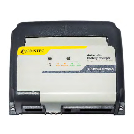
Page 9: Overview Presentation
The user interface zone • The energy conversion zone (all maintenance in this area is forbidden except with CRISTEC authorization, under penalty of warranty termination) Fixing of the charger is made by 4 x M5 round head screws (screw head diameter less than 10 mm). -
Page 10: Installation
47 to 65Hz. Generators The CRISTEC battery chargers are designed to operate from a generator. Be careful : In some cases, the generators can produce high over voltages, in particular during start-up phase. Before connecting the charger, please check its compatibility with the characteristics of the generator : power, voltage, overvoltage, frequency, current, etc. - Page 11 The type of cable (H07-VK, MX, etc.) should be defined by the installer according to the application type and applicable standards. For applications where the electricity network may be either 115VAC or 230VAC, always choose the cross section recommended for 115VAC. Always use cable markers without insulating collars in accordance with installation standards governing AC network input connections.
-
Page 12: Battery Cable
3.2.2 Battery cable Disconnect batteries before any wiring and junction of the connector. Please check the compatibility of voltage, current and setting according to the battery type before switching ON the charger. Checking of the charge voltage Before connecting the batteries to the charger, first check their polarity. Equally check the battery voltage with a calibrated voltmeter. -
Page 13: Precautions Regarding Electromagnetic Disturbance Generated By The Appliance
3.2.3 Precautions regarding electromagnetic disturbance generated by the appliance We recommend a minimum distance of 2m between the charger and any potentially sensitive equipment. Use shielded cables for all the connections (*). The shielding should be earthed at both the transmitting and the receiving ends. -
Page 14: Switches Setting - Adjustment - Indicators
WITCHES SETTING ADJUSTMENT INDICATORS 3.3.1 Description The YPOWER chargers are equipped with switches to configure the charger according the battery type and the application. 1 = ON 0 = OFF 2 charging modes are available : The BOOST function enables a faster charge of the batteries. This function is timed controlled (see table here after) and is automatically switched off when the battery is fully charged : BOOST stops when batteries current <... -
Page 15: Setting According To The Batteries Type
3.3.2 Setting according to the batteries type Maximum Maximum Description of the Voltage* with Voltage* with duration of duration of Switches setting battery type BOOST OFF BOOST ON BOOST at ABSOPTION at +/- 5% T +/- 5% T BOOST Opened type bat 13.4V 14.1V free electrolyte (wet) -
Page 16: Factory Setting
For special batteries, call in a professional installer, who will make the specific settings in accordance with the battery manufacturer's specifications and according to the specifics of the installation. CRISTEC is not liable for any damage caused to the batteries or for inefficient recharging. -
Page 17: Charging Curve
3.3.5 Charging curve BOOST in ON position With this setting the YPOWER charger delivers a 5-step charge curve IUoU + automatic weekly recycling (switch E) + return to automatic BOOST : BOOST, ABSORPTION, FLOATING + REFRESH, REBOOST. V BOOST : BOOST voltage (see table above) V FLOAT : FLOATING voltage (see table above : voltage with no BOOST) -
Page 18: Indicators
REFRESH phase : It is an automatic weekly cycle (Inhibited or not by means of switch F) in order to optimize the battery life duration. It will occur only after a complete recharge cycle (BOOST, ABSORPTION and FLOATING).The charger will generate automatically a safe timed voltage step every 7 days whatever the position of BOOST switch. -
Page 19: Equipment Maintenance And Repairs
Disconnect the battery charger from the AC power network and disconnect the batteries before undertaking any repairs. When fuses have blown, only use fuses of the type and size recommended in this manual. Please contact CRISTEC or their distributor for any other repairs. Any repair without CRISTEC prior agreement entails an exclusion of warranty. -
Page 20: Technical Specifications
TECHNICAL SPECIFICATIONS YPO 12V-16A, 12V-25A, 24V12A Part Number YPO12-16 YPO12-25 YPO24-12 Model 12V/16A 12V/25A 24V/12A recommended battery bank (Ah) 100-200Ah 200-300Ah 100-200Ah Input from 90 to 265VAC single-phase automatic Voltage Frequency from 47 to 65Hz automatic Input current consumption 1.1/2.2A 1.7/3.4A 1.7/3.4A 230/115VAC... - Page 21 YPO 12V-40A, 12V-60A, 24V20A, 24V 30A Part Number YPO12-40 YPO12-60 YPO24-20 YPO24-30 Model 12V/40A 12V/60A 24V/20A 24V/30A recommended battery bank (Ah) 300-500Ah 500-700Ah 200-300h 300-500Ah Input Voltage from 90 to 265VAC single-phase automatic Frequency from 47 to 65Hz automatic Input current consumption 2.7/5.6A 4.4/8.7A 2.9/5.9A...
- Page 22 Appendix Anhang Anexo...
- Page 23 ANNEXE 1 / APPENDIX 1 / ANHANG 1 / ANEXO 1 / ALLEGATO 1 YPO 12-16 - 12-25 – 24-12 Entrée / Input / Eingang / Entrada / Ingresso: K1 • PE : Terre / Earth / Erde / Tierra / Terra ACN : Neutre / Neutral / Neutralleiter / Neutro / Neutro •...
- Page 24 ANNEXE 2 / APPENDIX 2 / ANHANG 2 / ANEXO 2 / ALLEGATO 2 YPO 12-40 – 12-60 – 24-20 – 24-30 Entrée / Input / Eingang / Entrada / Ingresso: K1 • PE : Terre / Earth / Erde / Tierra / Terra ACN : Neutre / Neutral / Neutralleiter / Neutro / Neutro •...
- Page 25 ANNEXE 3 / APPENDIX 3 / ANHANG 3 / ANEXO 3/ ALLEGATO 3 YPO 12-16 - 12-25 – 24-12 Positionner le chargeur à la verticale, connection vers le bas. Le non respect de cette position peut entrainer une diminution de la puissance disponible, une perte de degré d’IP. Place the charger vertically, connection downwards.
- Page 26 ANNEXE 4 / APPENDIX 4 / ANHANG 4 / ANEXO 4 / ALLEGATO 4 YPO 12-40 – 24-20 – 24-30 Positionner le chargeur à la verticale, connection vers le bas. Le non respect de cette position peut entrainer une diminution de la puissance disponible, une perte de degré d’IP. Place the charger vertically, connection downwards.
- Page 27 ANNEXE 5 / APPENDIX 5 / ANHANG 5 / ANEXO 5 / ALLEGATO 5 YPO 12-60 Positionner le chargeur à la verticale, connection vers le bas. Le non respect de cette position peut entrainer une diminution de la puissance disponible, une perte de degré d’IP. Place the charger vertically, connection downwards.
- Page 28 ANNEXE 6 / APPENDIX 6 / ANHANG 6 / ANEXO 6 / ALLEGATO 6 Autres Cablages /Other type of installation / Andere Kabelungen / Otros Cableados / Altri tipi di cablaggio • Batterie de démarrage / +Engine battery / + Startbatterie / + batería de arranque / + batteria di avviamento ❶...
- Page 29 ❺ Montage 2 Batteries Service Mounting 2 Auxiliary Batteries Montage 2 Hilfsbatterien Montaje 2 Baterías Servicio Montaggio 2 Batterie Servizio ❻ Montage 3 Batteries Service Mounting 3 Auxiliary Batteries Montage 3 Hilfsbatterien Montaje 3 Baterías Servicio Montaggio 3 batterie Servizio...
Need help?
Do you have a question about the YPOWER 12V/25A and is the answer not in the manual?
Questions and answers