Cristec YPOWER+ 12V-40A Manual
Hide thumbs
Also See for YPOWER+ 12V-40A:
- User manual (96 pages) ,
- User manual (80 pages) ,
- User manual (30 pages)
Chapters

Related Manuals for Cristec YPOWER+ 12V-40A


Summary of Contents for Cristec YPOWER+ 12V-40A
- Page 1 Manuel utilisateur de l’unité d’énergie Modèles 12V / 40A et 12V / 60A S.A.S. CRISTEC 31 rue Marcel Paul - Z.I. Kerdroniou Est 29000 QUIMPER - FRANCE E-mail: info@cristec.fr https://www.cristec.fr UEYPOPL-A...
- Page 2 UEYPO+_1 Manuel d'utilisation en Français User Manual in English...
-
Page 3: Table Of Contents
SOMMAIRE PRECAUTIONS – GARANTIE ........................3 PRECAUTIONS (MISE EN GARDE) – DISPOSITIONS RELATIVES A LA SECURITE ........3 GARANTIE ............................. 9 FONCTIONNEMENT–PRESENTATION–INTERFACES ................10 PRINCIPE DE FONCTIONNEMENT ....................... 10 PRESENTATION GENERALE ......................... 10 DIAGRAMME FONCTIONNEL ......................11 INSTALLATION ............................ 12 ENCOMBREMENT ET POIDS DE L’UNITE D’ENERGIE ................ -
Page 4: Precautions - Garantie
Ce manuel doit être conservé avec soin et consulté avant toute intervention car il contient toutes les informations relatives à l'utilisation de l'appareil. Ce document est la propriété de CRISTEC; toutes les informations contenues dans ce document s'appliquent au produit qui l'accompagne. La société se réserve le droit d'en modifier les spécifications sans préavis. - Page 5 S’ils (ou elles) sont correctement surveillé(e)s et si des instructions relatives à l'utilisation de l'appareil en toute sécurité leur ont été données, et si les risques encourus ont été appréhendés, alors ils (ou elles) pourront l’utiliser sous la surveillance d’une personne responsable. Les enfants ne doivent pas jouer avec l’appareil.
- Page 6 Disposition générale Avant toute manipulation de l’unité d’énergie, il est impératif de lire attentivement ce manuel. Dispositions vis à vis des chocs électriques Risque d’électrocution et de danger de mort : il est formellement interdit d’intervenir dans l’unité d’énergie sous tension. Abaisser le disjoncteur différentiel ne suffit pas, il faut impérativement débrancher la connexion au réseau électrique.
- Page 7 Des précautions particulières sont recommandées sur toute installation susceptible craindre phénomènes d’électrolyse. La réglementation impose la présence de coupe-batteries au plus près des batteries. Dispositions vis à vis des chocs de foudre Dans les zones géographiques fortement exposées, il peut être utile de placer un parafoudre en amont du dispositif afin d'éviter toute dégradation irréversible de ce dernier.
- Page 8 Attention surface chaude : ne pas toucher l’unité d’énergie pendant et après son fonctionnement (risque de brûlure). Dispositions vis à vis des poussières, du ruissellement et chutes d'eau L'emplacement de l’unité d’énergie doit être choisi pour éviter toute pénétration d’humidité, de liquide, de sel ou de poussières dans l’unité.
- Page 9 Fusibles Les fusibles de sortie CC doivent être remplacés uniquement par le fusible approprié : Libellé et quantité (voir section 5.3): Fabricant : Bussmann / EATON Référence : ATM 20 /ATM30 /ATM15 Autres dispositions Ne pas percer ou usiner le coffret de l’unité d’énergie : risque de casse de composants ou de projection de copeaux ou limailles sur la carte de l’unité...
-
Page 10: Garantie
: les frais de port et d’emballage, les frais de démontage, remontage et tests, ainsi que tous les autres frais non cités. Notre garantie ne peut en aucun cas donner lieu à une indemnité. CRISTEC ne peut être tenu pour responsable des dommages dus à l'utilisation de l’unité d’énergie. -
Page 11: Fonctionnement-Presentation-Interfaces
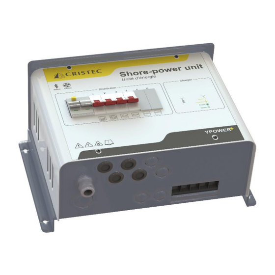
INTERFACES RINCIPE DE FONCTIONNEMENT Les unités d’énergie CRISTEC permettent de disposer dans un même coffret de la protection AC du bord et d’un chargeur de batteries. L’ensemble répond aux normes européennes en vigueur et permet, grâce à son coffret compact, d’optimiser l’encombrement et le temps de montage. -
Page 12: Diagramme Fonctionnel
IAGRAMME FONCTIONNEL CONNECTIQUE : Liaison équipotentielle terre/DC (côté dissipateur) Presse-étoupe Passe-câbles Entrée AC Sorties AC Bornier à vis Sorties DC... -
Page 13: Encombrement Et Poids De L'unite D'energie
NSTALLATION Ce paragraphe traite des dispositions relatives à l'installation de l'équipement. L'installation et la première mise en fonctionnement doivent être assurées par un électricien ou un installateur professionnel selon les normes en vigueur (dans le cas des navires de plaisance, se conformer à la norme internationale ISO13297). -
Page 14: Installation Typique
Consulter CRISTEC pour toute utilisation en 115VCA 60Hz. Groupes électrogènes Les unités d’énergie CRISTEC sont conçues pour fonctionner sur groupe électrogène. Attention : Dans certains cas, les groupes électrogènes peuvent générer des surtensions importantes, en particulier dans leur phase de démarrage. Avant raccordement de l’unité... -
Page 15: Cable De Liaison Distribution Alternatif
Le câble d’alimentation doit comporter 3 conducteurs de couleurs (préconisées par la norme NFC 15-100). Ils devront être obligatoirement de section correspondant au calibre du disjoncteur différentiel situé en aval et se connecter sur les bornes à vis leur correspondant (L avec phase, N avec neutre, terre avec terre). Le type de câble (H07-VK, MX, etc.) devra être défini par l’installateur en fonction du type d’application et des normes applicables. -
Page 16: Cable De Liaison Batteries
Le conducteur PE (communément appelé « terre », fil vert/jaune) de la source alternative doit impérativement être raccordé sur les borniers de terre (jaune et vert à droite sur le rail DIN) à cet effet et avant toute autre borne (barre de terre). -
Page 17: Configuration De Lunite Denergie
Les câbles doivent assurer uniquement l'alimentation de l'appareil. Une dérivation ou un pontage afin d'alimenter un autre appareil sont à prohiber. Ceci est un conseil d'installation et non une obligation. L'électricien installateur décide, compte tenu de l'environnement CEM, de l'emploi de câble blindé ou non. ’... - Page 18 DEROULEMENT DE LA PROGRAMMATION Chargeur en fonctionnement Appuyez sur le bouton ‘’P’’ Appuyez sur le bouton ‘’P’’ plus de 1 seconde plus de 1 seconde pour entrer pour enregistrer les modifications en mode programmation et reprendre la charge Champ 3 Champ 1 Réglage Réglage...
-
Page 19: Champ De Programmation 1 : Modifier Le Type De Batterie
3.3.2 Champ de programmation 1 : Modifier le type de batterie Configuration en fonction du type de batteries Durée maximale Durée maximale Tension de Tension de Programmation Désignation du type FLOATING BOOST de batteries BOOST à +/- 5% l’absorption à +/- 5% T BOOST Bat type ouverte... -
Page 20: Champ De Programmation 3 : Selection De Protocole Bus-Can
PBUS PTIONS ET FONCTIONNALITES 3.4.1 Bluetooth L’application Bluetooth Cristec Connect est disponible sur l’Apple Store et Play Store permettant la connexion sans fil à distance à l’appareil, cette application permet la supervision et la configuration de l’appareil. 3.4.2 Compensation en température (en option) Les sondes STP-UNI-2.8 et STP-UNI-5.0 permettent la compensation de la tension d’Absorption et de la... -
Page 21: Bus-Can
3.4.4 Bus-CAN Les chargeurs sont équipés de deux embases compatibles avec les connecteurs Molex Microfit 3.0, 6 points de référence 43045-0600. La documentation n°1336205REG_CAN concernant le Bus-CAN (spécification matérielle et logicielle) est disponible sur demande. Protocole Le protocole CAN peut être choisi avec le champ de programmation 3 (voir 3.3.4). Cavaliers JP1 et JP2 Alimentation L’alimentation du BUS-CAN peut soit être effectuée par un autre équipement,... -
Page 22: Mode Standby
En cas de batteries spéciales, se référer à un installateur professionnel qui effectuera les réglages particuliers en accord avec les spécifications du constructeur de batteries et en tenant compte des particularités de l'installation. CRISTEC décline toute responsabilité en cas de détérioration des batteries ou de mauvaise recharge. -
Page 23: Courbe De Charge
OURBE DE CHARGE BOOST en position ON l’unité d’énergie Dans cette configuration, délivre une courbe de charge 5 états IUoU + Recyclage hebdomadaire automatique (Voir section 3.3.2.) + Retour BOOST automatique : BOOST, ABSORPTION, FLOATING + REFRESH, REBOOST. V BOOST : Tension de BOOST (voir tableau de la section 3.3.2) V FLOAT : Tension de FLOATING (voir tableau de la section 3.3.2 : tension sans BOOST) - Page 24 Il intervient uniquement après un cycle de recharge complète (BOOST, ABSORPTION et FLOATING). L’unité d’énergie va automatiquement générer un échelon de tension temporisé tous les 7 jours même si la phase REFRESH est inhibée (Voir section 3.3.3). Phase REBOOST : Phase automatique qui consiste à...
-
Page 25: Indicateurs
NDICATEURS Ces indicateurs (LED) sont visibles en façade de l'appareil au travers de guides de lumière et permettent une visualisation du mode de fonctionnement de l'appareil. Mode Etat des LED Etat de l’unité d’énergie Chargeur sous tension En charge Mode stand-by (voir section 3.4.5) LED 1 "ON"... -
Page 26: Dispositions Relatives A La Maintenance Et A La Reparation
En cas de rupture des fusibles, respecter le calibre et le type de fusible préconisés dans la présente notice. Pour toute autre intervention de réparation, contacter un revendeur ou la société CRISTEC. Toute réparation sans l’accord préalable de CRISTEC entraine une exclusion de garantie. -
Page 27: Specifications Techniques
2,3 ou 4 (voir nomenclature 5.4) 10A par sortie maximum Courant de sortie Total maximum cumulé= 16A Disjoncteur Ph + N, 10A Disjoncteur de sortie Nombre = 2, 3 ou 4 (voir nomenclature 5.4) Consulter CRISTEC pour toute utilisation en 115VCA 60Hz. -
Page 28: Nomenclature Des Unites D'energie
12V-40A 12V-60A ONCTION CHARGEUR MODELES Modèle 12V-40A 12V-60A Capacité batterie conseillée 300-500Ah 500-700Ah Entrée Tension De 90 à 265VAC monophasé automatique Fréquence De 47 à 65Hz automatique consommation à 230/115 VCA 2.7/5.6A 4.4/8.7A Facteur de puissance Rendement Supérieur à 90% Fusibles d’entrée T15A/250V –... - Page 29 CONTENTS PRECAUTIONS – WARRANTY ......................30 PRECAUTIONS (WARNING) – PROVISIONS RELATING TO SAFETY ............ 30 WARRANTY............................36 OPERATING-PRESENTATION-INTERFACES ..................37 OPERATING PRINCIPLE ........................37 PRESENTATION GENERALE ....................... 37 FUNCTIONAL DIAGRAM ........................38 INSTALLATION ..........................39 SHORE-POWER UNIT SIZE AND WEIGHT ..................39 WIRING .............................
-
Page 30: Precautions - Warranty
This manual should be kept safely and consulted before attempting any repairs because it contains all the information required to use the appliance. This document is the property of CRISTEC; all the information it contains applies to the accompanying product. CRISTEC reserves the right to modify the specifications without notice. - Page 31 supervision or instruction concerning use of the appliance by a person responsible for their safety. Children should be supervised to ensure that they do not play with the appliance.
- Page 32 Main precaution Before handling the shore-power unit, please read carefully this manual. Precautions regarding electric shocks Risk of electric shock and danger of death: it’s strictly forbidden to open the shore-power unit under voltage (except to configure the charger with the push-button). Lowering the differential circuit breaker is not enough, it is imperative to disconnect from the AC network.
- Page 33 Special precautions should be taken on any installation prone to electrolyze phenomena. Electrical standard requires a battery switch as close as possible to the batteries. Precautions regarding lightning In areas highly exposed to lightning, it may be advisable to install a lightning arrestor upstream of charger to safeguard it against irreversible damage.
- Page 34 Precautions regarding dust, seepage and falling water The shore-power unit should be located so as to prevent penetration of damp, liquid, salt and dust, any of which could cause irreparable damage to the equipment and be potentially hazardous for the user. The appliance should be installed in a dry and well-ventilated place.
- Page 35 Other precautions Never attempt to drill or to machine the shore-power unit's case: this may damage components or cause metal chips or filings to fall on the unit's board. Do not do anything that is not explicitly stated in this manual.
-
Page 36: Warranty
The warranty is valid for 36 months. The warranty applies if the cause of the failure is an internal defect in the shore-power unit that falls to CRISTEC. The warranty applies for equipment returned to the Quimper plant (France). -
Page 37: Operating-Presentation-Interfaces
NTERFACES PERATING PRINCIPLE CRISTEC shore-power unit combines AC protection and distribution, as well as a battery charger in the same box. The assembly complies with the European standards in force and, thanks to its compact size, optimizes space and assembly time. -
Page 38: Functional Diagram
UNCTIONAL DIAGRAM CONNEXIONS: Protection earth coonnector (back view) Cable gland Grommets AC input AC outputs screw terminal block DC outputs... -
Page 39: Installation
NSTALLATION This paragraph deals with the installation of the equipment. Installation and initial commissioning should be carried out by an electrician or professional installer in accordance with the standards currently in force (for pleasure boats the applicable international standard is ISO13297). The installer should familiarize himself with this operating manual and inform users of the instructions for use and the safety warnings set out in the manual. -
Page 40: Typical Installation
(1) Consult CRISTEC for any use at 115VAC 60Hz. Generators CRISTEC shore-power units are designed to operate from a generator. Be careful: In some cases, the generators can produce high over voltages, in particular during start-up phase. Before connecting the charger, please check its compatibility with the characteristics of the generator: power, voltage, overvoltage, frequency, current, etc. -
Page 41: Ac Output Cables
The power cable must have 3 colored conductors (recommended by the NFC 15-100 standard). They must have a section regarding to the rating of the RCD located downstream and be connected to the corresponding screw terminals (L with line, N with neutral, earth with earth). The installer should choose the type of cable (H07-VK, MX, etc.) according to the type of application and the applicable standards. -
Page 42: Battery Cables
The current in these cables must not exceed the rating of the upstream circuit breakers. The PE conductor (commonly called "earth", green/yellow wire) of the AC input network must imperatively be connected to the earth terminals (yellow and green on the right on the DIN rail) before any other terminal (earth busbar). -
Page 43: Configuration - Adjustment - Indicators
This is a recommendation for installation rather than an obligation. The installing electrician should decide whether or not to use shielded cable depending on the EMC environment. – ONFIGURATION DJUSTMENT INDICATORS You can see the battery configuration by turning off the CDR and back on. The number of flashes of the right LED gives you the type of batteries for which the charger is intended (see 3.3.2). - Page 44 SETTING THE CHARGER Charger working Press Push-button ‘’P’’ Press Push-button ‘’P’’ More than 1 sec to save the More than 1 sec to enter to configuration Configuration mode Programming Field 3 Programming Field 1 Value Value Short Short Push Short Push on on ‘‘P’’...
-
Page 45: Programming Field 1: Select Battery Type
3.3.2 Programming Field 1: Select battery type Configuration according to type of batteries 12V = Maximum Maximum FLOATING BOOST Description of the battery duration of duration of Setting voltage voltage type BOOST at ABSOPTION at +/- 5% T +/- 5% T BOOST Opened type bat 13.4V... -
Page 46: Programming Field 3: Can-Bus Protocols
PBUS PTIONS AND FEATURES 3.4.1 Bluetooth The Cristec Connect Bluetooth application is available on the Apple Store and Play Store allowing remote wireless connection to the device, this application allows monitoring and configuration of the device. 3.4.2 Thermal compensation (Optional) STP-UNI-2.8 and STP-UNI-5.0 temperature probes enable the compensation of Absorption voltage... -
Page 47: Canbus
3.4.4 CANBUS battery chargers have two terminals made for connectors Molex Microfit 3.0, 6 circuits (reference 43045- 0600). Documentation n° 1336205REG_CAN (hardware and software specification) is available upon request. Protocol CAN-Bus protocol can be chosen with the programming field 3 (see 3.3.4). Jumpers JP1 et JP2 Power Supply The power supply of the CAN-Bus can either be carried out by another... -
Page 48: Standby Mode
To define the charge in function of your battery, please refer to the chart, paragraph: 3.3.2. For specific batteries, please call a professional installer, who will make the specific settings in accordance with battery manufacturer's specifications and installation characteristics. CRISTEC is not liable for any damage caused to the batteries or for inefficient recharging. -
Page 49: Charging Curve
HARGING CURVE BOOST in ON position With this setting, the charger delivers a 5-step charge curve IUoU + automatic weekly recycling (“P” button see section 3.3.2) + return to automatic BOOST: BOOST, ABSORPTION, FLOATING + REFRESH, REBOOST. V BOOST: BOOST voltage (see section 3.3.3) V FLOAT: FLOATING voltage (see section 3.3.3: voltage with no BOOST) T BOOST:... - Page 50 It will occur only after a complete recharge cycle (BOOST, ABSORPTION and FLOATING). The charger will generate automatically a safe timed voltage step every 7 days even if REFRESH phase is off (see section 3.3.3). Phase REBOOST: Automatic phase consisting in coming back to a BOOST voltage if the DC utilizations require it (i.e., after a complete recharge cycle BOOST, ABSORPTION and FLOATING if some DC constant consumptions are detected the charger will restart a new complete charge cycle including a BOOST phase).
-
Page 51: Indicators
NDICATORS The following LED indicators are visible on the front of the appliance for monitoring. Mode LEDs Charger status Charger is ON Charging Stand-by mode (see section Erreur ! Source du renvoi introuvable.) LED 1 "ON" Programming Programming (see section 3.3) No or poor-quality AC current Fault Input fuse is blown... -
Page 52: Equipement Maintenance And Erpairs
Disconnect the battery charger from the AC power network and disconnect the batteries before undertaking any repairs. When fuses have blown, only use fuses of the type and size recommended in this manual. Please contact CRISTEC or their distributor for any other repairs. Any repair without CRISTEC prior agreement entails an exclusion of warranty. -
Page 53: Technical Specifications
10A or 16A per output Output current Maximum 16A total (or 32A on US versions) double pole circuit breaker 10A or 16A Output circuit breaker Number = 2, 3 or 4 (depending on model see 5.4) Consult CRISTEC for any use at 115VAC 60Hz. -
Page 54: Charger Features
HARGER FEATURES Part Number 12V-40A 12V-60A recommended battery bank* 300-500Ah 500-700Ah Input Voltage from 90 to 265VAC single-phase automatic Frequency from 47 to 65Hz automatic Input current consumption 230/115VAC 2.7/5.6A 4.4/8.7A Power factor Efficiency Greater than 90% T15A/250V – 6.3 x 32 (F101) Input fuses Output 4 separate positive terminals : +BAT E, +BAT 1 et +BAT 2 +BAT3 (integrated Mosfet...
Need help?
Do you have a question about the YPOWER+ 12V-40A and is the answer not in the manual?
Questions and answers