Table of Contents
Advertisement
Quick Links
CS-242 ClearSky® Outdoor Wireless Contact Sensor
Installation Instructions & User Manual
Specifications
Frequency: 345 MHz
Battery: 2X 1.5V AA Lithium Cell
Battery life: up to 10 years
Magnet gap: 2 inch max
Package Contents
1x Sensor
1x Magnet
2x 1" Screws for Sensor Mount
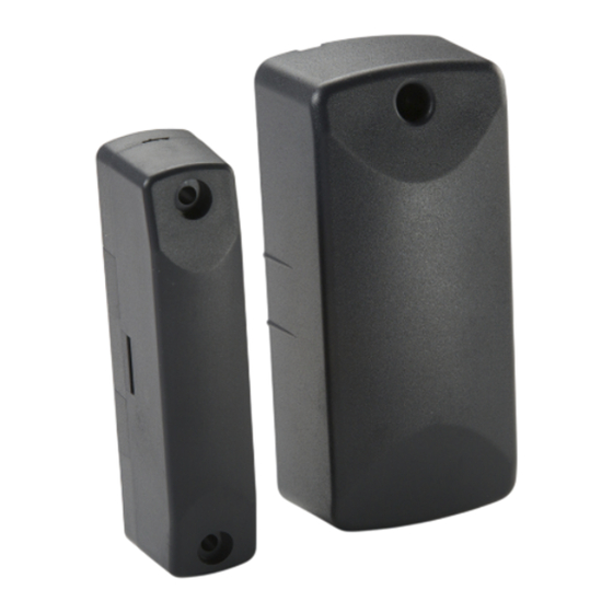
Component Identification
Main Sensor Body
Enrolling
To enroll the sensor, set your panel into program mode, refer to your specific alarm panel manual
for details on these menus. When prompted by the panel, trigger the sensor by moving the
magnet in and out of range of the sensor. The panel will beep when you have successfully learned
in a sensor.
External Input: An external contact may also be connected to the
CS-242 with the supplied wiring connector. The external input is
located in the main sensor body near the battery terminals.
N.C is for a normally closed switch. COM is for common
terminal. N.O is for normally opened switch.
Operating Temperature: -40°to 60°C
Operating Humidity: 5-95% RH non condensing
Compatible with ClearSky receivers
Supervisory signal interval: 60 min (approx.)
Rubber insert
2x 1.5" Screws for Magnet Mount
2x Lithium AA Batteries
1x Manual
Back mounting plate
Magnet
N.C. COM. N.O.
N.C. COM. N.O.
Advertisement
Table of Contents

Related Manuals for Ecolink ClearSky CS-242


Summary of Contents for Ecolink ClearSky CS-242
- Page 1 CS-242 ClearSky® Outdoor Wireless Contact Sensor Installation Instructions & User Manual Specifications Frequency: 345 MHz Operating Temperature: -40°to 60°C Battery: 2X 1.5V AA Lithium Cell Operating Humidity: 5-95% RH non condensing Battery life: up to 10 years Compatible with ClearSky receivers Magnet gap: 2 inch max Supervisory signal interval: 60 min (approx.) Package Contents...
- Page 2 Installation Mounting Sensor & Magnet Use screws or cable ties to secure the contact and the magnet. Cable Tie Mounting Points Determine mounting location for sensor and magnet. Take into consideration the magnet mounting location. The magnet must be facing the main sensor body marked by the 2 lines. If using the external input, please refer to External Wiring with External Input directions.
- Page 3 External Wiring with External Input Note: Use a minimum of 22AWG jacked cable wire or 26AWG solid copper leads. Maximum wire length cannot exceed 5 feet. Strip cable jacket back approx. 6 inches to allow enough length when removing the sensor body from back mounting plate and rubber insert.
- Page 4 IC: 9863B-WST242 Warranty Ecolink Intelligent Technology Inc. warrants that for a period of 1 years from the date of purchase that this product is free from defects in material and workmanship. This warranty does not apply to damage caused by shipping or handling, or damage caused by accident, abuse, misuse, misapplication, ordinary wear, improper maintenance, failure to follow instructions or as a result of any unauthorized modifications.
Need help?
Do you have a question about the ClearSky CS-242 and is the answer not in the manual?
Questions and answers