
Related Manuals for Dolphin Charger PREMIUM Series


Summary of Contents for Dolphin Charger PREMIUM Series
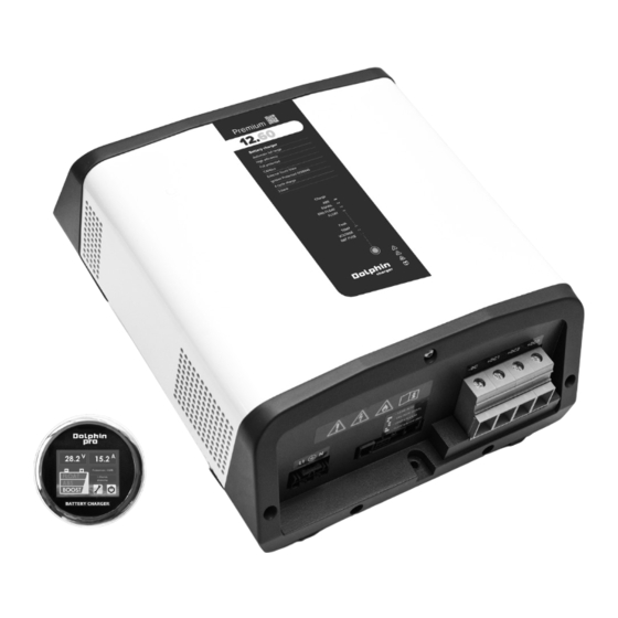
- Page 1 MANUEL D’UTILISATION Série PREMIUM Chargeurs de batteries premium 12V60A Code : 399050 premium 24V30A Code : 399060...
- Page 2 NOT-PREMIUM900W-04...
-
Page 3: Précautions D'installation
PRÉCAUTIONS DE SÉCURITÉ ATTENTION AFIN DE PREVENIR TOUT RISQUE DE CHOC ELECTRIQUE OU D’INCENDIE, LIRE ATTENTIVEMENT CE MANUEL AVANT D’INSTALLER L’APPAREIL En cas de problème ou d’incompréhension, contacter votre revendeur. Cet appareil n’est pas prévu pour être utilisé par des personnes (y compris les enfants) dont les capacités physiques, sensorielles ou mentales sont réduites, ou des personnes dénuées d’expérience ou de connaissance, sauf si elles ont pu bénéficier... - Page 4 ATTENTION convection. Cet appareil ne doit pas être exposé aux ruissellements, aux projections d’eau et aux poussières de toutes natures. Il est fortement recommandé de fixer l’appareil en position verticale, la sortie des câbles orientée vers le bas. La prise secteur ainsi que le connecteur batterie doivent impérativement rester accessibles et manœuvrables une fois le matériel installé.
- Page 5 ATTENTION Pour des raisons de sécurité, la borne de TERRE de cet appareil (borne PE « Protective Earth »), doit impérativement être raccordée à la terre générale de l’installation (fil vert/jaune du câble secteur). Se référer pour cela au plan de raccordements. Pour prévenir tout échauffement parasite, veiller à...
- Page 6 PRÉCAUTIONS DE SÉCURITÉ ATTENTION D’autre part, cet appareil émet des interférences conduites et rayonnées dont les niveaux sont conformes à la réglementation en vigueur. Veillez à ce que les autres matériels utilisés à proximité soient compatibles d’un point de vue susceptibilité...
- Page 7 PRÉCAUTIONS DE SÉCURITÉ ATTENTION Précautions de maintenance Afin de prévenir tout risque de choc électrique lors des opérations de maintenance, veillez à suivre de manière impérative les recommandations qui suivent avant d’intervenir dans l’appareil : Cet appareil n’est pas démontable et la carte électronique de ce fait non accessible.
-
Page 8: Spécifications Techniques
SPÉCIFICATIONS TECHNIQUES 12V60A 24V30A CARACTERISTIQUES DE SORTIES Nb de sorties 3 sorties isolées 4 choix possibles par commutateur Nb de courbes type dip-switch Type de courbes IUUo Profil de charge Type de batterie : Plomb ouvert Courbe n°1 V.boost = 14,2V = 28,4V Pb ouvert V.float = 13,2V... - Page 9 SPÉCIFICATIONS TECHNIQUES 12V60A 24V30A GÉNÉRALITÉS LED en façade ou afficheur Affichage TOUCH à distance (en option) Température -10°C à +50°C Stockage -20°C à +70°C Humidité 10% à 90% (sans condensation) Ventilation Forcée & thermostatée Com. externe CANbus, protocole propriétaire EN61000-6-3 et EN61000-6-1 EN60335-2-29 (2002) Sécurité...
-
Page 10: Mode De Fonctionnement
MODE DE FONCTIONNEMENT MODE STATUS Absorption Jaune Les batteries sont en cours de fixe recharge. La durée de la phase d’absorption est variable mais limitée à 6 heures, selon l’état de charge initiale des batteries. Equalisation Jaune Les batteries sont en fin de clignot. - Page 11 RACCORDEMENTS LED de façade Fusibles batterie au dos Entrée secteur Sorties batteries TOUCH view_RJ11 CANbus_MicroFit Sélecteur de charge UART_RJ12 NOT-PREMIUM900W-04...
-
Page 12: Schéma De Raccordement
RACCORDEMENTS Schéma de raccordement Distribution BusBar (-) Montage du connecteur alimentation secteur Étape 1 Dénuder le câble sur environ 3 cm Dénuder les 3 fils sur environ 8 mm Etamer les extrémités en cuivre nu Étape 2 Enlever l’opercule du capot à l’aide d’un cutter Étape 3 Passer le câble dans le capot Étape 4... -
Page 13: Installation
INSTALLATION Dimensions 3x 17,3 Tolérances Générales dimensions : angles : 07/03/2016 Création états de surface : DATES Ind. Matière : Contrôle Qualité Instructions particulières : (Conforme RoHS) HELLE 1 : 5 21 Porte du grand Lyon PLAN N° Désignation : 01707 MIRIBEL CEDEX mdpcontact@mdpmotor.com DOL PRO 900W... -
Page 14: Garantie
GARANTIE AFIN DE PREVENIR TOUT RISQUE DE MAUVAISE UTILISATION DE L’APPAREIL, LIRE ATTENTIVEMENT LA LISTE DES EVENEMENTS OU DEFAUTS POTENTIELS NON COUVERTS PAR LA GARANTIE PRODUIT Cet appareil n’est pas protégé contre les inversions de polarités batterie. Risque de dommages irréversibles sur le matériel. Chute mécanique de l’appareil pouvant entraîner des déformations irréversibles du coffret ainsi que le «... - Page 15 GARANTIE Projections ou ruissellements d’eau à l’intérieur de l’appareil pouvant entraîner des dysfonctionnements irréversibles sur le plan électronique. Précautions de mise au rebut Cet appareil contient des composants électroniques et des matériaux qui doiventimpérativement subir un recyclage en fin de vie du produit, dans un but de préservation de l’environnement.
- Page 16 2, Chemin de Branchy 74600 ANNECY France contact@dolphin-charger.com www.dolphin-charger.com...
-
Page 17: Battery Charger
OPERATING & USERS MANUAL PREMIUM Series Battery charger premium 12V60A Code : 399050 premium 24V30A Code : 399060... - Page 18 NOT-PREMIUM900W-04...
-
Page 19: Installation Precautions
SAFETY PRECAUTIONS WARNING TO PREVENT ANY RISK OF ELECTRIC SHOCK OR FIRE, READ THIS MANUAL CAREFULLY BEFORE INSTALLING THE EQUIPMENT. In the event of any problems or misunderstandings, please contact your dealer. This equipment is not designed for use by people (including children) with diminished physical, sensorial or mental capacities, or people without experience or knowledge of such equipment,... -
Page 20: Connection Precautions
WARNING All electrical connections to and from the charger must remain accessible at all times. This system should not be exposed to water or dust. It is strictly forbidden to tamper with the system casing in any way. This device is not a toy and must be kept out of the reach of children. - Page 21 WARNING All cable connections and connectors must be maintained in good condition. Once the connection of the AC cable has been completed, it is imperative to fit the Winsta Wago snap on security cover. See “Assembling the Shore Power Connector”. Activation precautions In order to avoid all risk of electric shock or irreversible damage to the device, please follow...
- Page 22 WARNING Device serial number The serial number appears on the grey or white sticker on one side of the device. This number is aligned vertically and comprises a first number indicating the year of manufacture (e.g.: 21 for 2021), a letter indicating the month of manufacture (e.g.: C for the month of March), as well as a 5-figure number that is the product’s individual serial number.
-
Page 23: Maintenance Precautions
WARNING Maintenance precautions To prevent any risk of electric shock during maintenance operations, ensure that the following recommendations are scrupulously observed before performing any maintenance on the device: This device cannot be dismantled and thus the PC board is inaccessible. It is strictly forbidden to dismantle the housing for any reason. -
Page 24: Technical Specifications
TECHNICAL SPECIFICATIONS 12V60A 24V30A OUTPUT Nb of outputs 3 isolated outputs Nb charging 4 possible charging curves. curves Selection by external dip-switch Curves types IUUo Charging profile Battery type: Lead open Charging curve 1 V.boost = 14,2V = 28,4V Lead open V.float = 13,2V = 26,4V Battery type: GEL, AGM, Spiral... - Page 25 TECHNICAL SPECIFICATIONS 12V60A 24V30A GENERAL Front LED or remote Display TOUCH View (option) Operating temp -10°C to +50°C Storage temp -20°C to +70°C Humidity 10% to 90% (without condensation) Ventilation Forced fan cooling External com CANbus EN61000-6-3 et EN61000-6-1 EN60335-2-29 (2002) Security ISO8846 (12V60A model) Housing...
-
Page 26: Operating Mode
OPERATING MODE MODE STATUS Absorption Steady The batteries are charging. Time yellow required to complete Absorp- tion mode varies depending on the initial status of the batteries, but is limited to 6 hours. Equalisation Yellow The batteries are coming to the blinking end of the charging cycle. - Page 27 CONNECTIONS Front LED Battery fuses under the product Main acces BAT acces TOUCH view_RJ11 CANbus_MicroFit Cycle charge selector UART_RJ12 NOT-PREMIUM900W-04...
-
Page 28: Wiring Diagram
CONNECTIONS Wiring diagram Dispatching BusBar (-) Assembling the shore power connector Step 1 Remove approx 3 cm of the outer sheath Remove approx 8 mm of the inner wires’ sheaths Tinplate the bare copper ends Step 2 Remove the security cap using an utility knife Step 3 Pull the conductor through the pre latched strain relief housing... - Page 29 INSTALLATION Dimensions 3x 17,3 Tolérances Générales dimensions : angles : 07/03/2016 Création états de surface : DATES Ind. Matière : Contrôle Qualité Instructions particulières : (Conforme RoHS) HELLE 1 : 5 21 Porte du grand Lyon PLAN N° Désignation : 01707 MIRIBEL CEDEX mdpcontact@mdpmotor.com DOL PRO 900W...
-
Page 30: Warranty
WARRANTY TO PREVENT ANY RISK OF INCORRECT USE OF THE DEVICE, CAREFULLY READ THE LIST OF POTENTIAL EVENTS OR FAULTS NOT COVERED BY THE PRODUCT WARRANTY This device is not protected against battery polarity reversals. Risk of irreversible damage to the equipment. - Page 31 WARRANTY Precautions for scrapping This device contains electronic components and materials that must be recycled at the end of the product’s usable life, for environmental reasons. At the end of their usable lives all devices must therefore be returned either to the local distributor or entrusted to a specialist electronic equipment recycling company.
- Page 32 2, Chemin de Branchy 74600 ANNECY France contact@dolphin-charger.com www.dolphin-charger.com...
Need help?
Do you have a question about the PREMIUM Series and is the answer not in the manual?
Questions and answers