Table of Contents
Advertisement
Quick Links
ACDEU
OM-05514−OE01
May 20, 2003
Rev. B 08-05-03
INSTALLATION, OPERATION,
AND MAINTENANCE MANUAL
WITH PARTS LIST
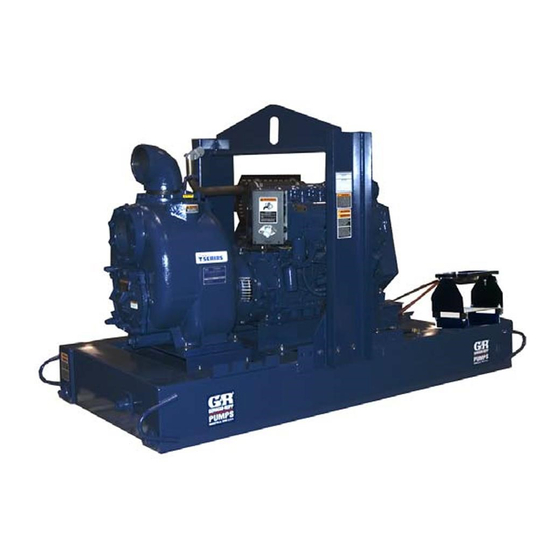
SUPER T SERIES PUMP
MODEL
T6A60S−F4L
THE GORMAN-RUPP COMPANY D MANSFIELD, OHIO
D
GORMAN-RUPP OF CANADA LIMITED
ST. THOMAS, ONTARIO, CANADA
Printed in U.S.A.
www.gormanrupp.com
E
Copyright by the Gorman-Rupp Company
Advertisement
Table of Contents

Related Manuals for GORMAN-RUPP SUPER T6A60S F4L


Summary of Contents for GORMAN-RUPP SUPER T6A60S F4L
- Page 1 Rev. B 08-05-03 INSTALLATION, OPERATION, AND MAINTENANCE MANUAL WITH PARTS LIST SUPER T SERIES PUMP MODEL T6A60S−F4L THE GORMAN-RUPP COMPANY D MANSFIELD, OHIO GORMAN-RUPP OF CANADA LIMITED ST. THOMAS, ONTARIO, CANADA Printed in U.S.A. www.gormanrupp.com Copyright by the Gorman-Rupp Company...
- Page 2 The engine exhaust from this product contains chemicals known to the State of California to cause cancer, birth defects or other reproductive harm.
-
Page 3: Table Of Contents
TABLE OF CONTENTS INTRODUCTION ..........PAGE I −... - Page 4 TABLE OF CONTENTS (continued) Horn Delay ............PAGE C −...
-
Page 5: Introduction
SUPER T SERIES OM−05514 INTRODUCTION Thank You for purchasing a Gorman-Rupp pump. neither operator safety nor pump integrity are com- Read this manual carefully to learn how to safely promised by the installation. Pumps and related install and operate your pump. Failure to do so... -
Page 6: Safety - Section A
SUPER T SERIES OM−05514 SAFETY - SECTION A This information applies to Super T Se- during automatic operation. Disconnect ries engine driven pumps. Refer to the the positive battery cable before per- manual accompanying the engine be- forming any maintenance. Failure to do fore attempting to begin operation. - Page 7 OM−05514 SUPER T SERIES Do not remove plates, covers, gauges, Fuel used by internal combustion en- pipe plugs, or fittings from an over- gines presents an extreme explosion heated pump. Vapor pressure within the and fire hazard. Make certain that all pump can cause parts being disen- fuel lines are securely connected and gaged to be ejected with great force.
-
Page 8: Installation − Section Bpage B
For further assistance, contact your Gorman-Rupp Most of the information pertains to a standard distributor or the Gorman-Rupp Company. static lift application where the pump is positioned above the free level of liquid to be pumped. -
Page 9: Battery Specifications And Installation
Check the shipping Gorman-Rupp distributor or the factory to deter- tag on the unit packaging for the actual weight, and mine the repair or updating policy. Do not put the use lifting equipment with appropriate capacity. -
Page 10: Suction And Discharge Piping
SUPER T SERIES OM−05514 If the pump has been mounted on a moveable Connections to Pump base, make certain the base is stationary by setting the brake and blocking the wheels before attempt- Before tightening a connecting flange, align it ex- actly with the pump port. -
Page 11: Sealing
OM−05514 SUPER T SERIES strainer furnished with the pump will also pass tion inlet because the inflow will carry air down into through the pump itself. the sump, and air entering the suction line will re- duce pump efficiency. If a strainer is not furnished with the pump, but is installed by the pump user, make certain that the If it is necessary to position inflow close to the suc- total area of the openings in the strainer is at least... -
Page 12: Float Switches
SUPER T SERIES OM−05514 Figure 2. Recommended Minimum Suction Line Submergence vs. Velocity FLOAT SWITCHES above the point where it bends along the bot- tom. Direct the suction line toward the flow, and the float(s) away from the flow. If a stand- Installation pipe is available, attach the float switch cable to the standpipe in the sump at the approxi-... -
Page 13: Optional Submersible Transducer
OM−05514 SUPER T SERIES ENGINE (0.9) CONTROL (.76) (Emptying) (0.6) (Filling) (.46) OPERATING (0.3) RANGE CABLE (See Table Below) TETHER (.15) POINT (Emptying) (0.3) (0.6) (0.9) (1.2) APPROXIMATE FREE CORD LENGTH IN FT. (M) 1.25" Pipe (Filling) (Not Furnished) Figure 3. Float Switch Data OPTIONAL SUBMERSIBLE above the point where it bends along the bot- tom. -
Page 14: Discharge Lines
SUPER T SERIES OM−05514 SUCTION LINE DISCHARGE LINE SIGNAL CABLE (ATTACH TO SUCTION LINE) SUCTION SUBMERSIBLE STRAINER TRANSDUCER (DOWNSTREAM FROM SUCTION) FLOW Figure 4. Typical Submersible Transducer Installation DISCHARGE LINES Siphoning If the application involves a high discharge head, gradually close the discharge Do not terminate the discharge line at a level lower throttling valve before stopping the pump. -
Page 15: Automatic Air Release Valve
Gorman-Rupp Automatic Air Release Valve be installed in the bypass line. AUTOMATIC AIR RELEASE VALVE Gorman-Rupp Automatic Air Release Valves are When properly installed and correctly adjusted to reliable, and require minimum maintenance. See the specific hydraulic operating conditions of the... -
Page 16: Air Release Valve Installation
É É decrease tension on the spring. Contact your Gor- man-Rupp distributor or the Gorman-Rupp Com- pany for information about an Automatic Air Re- lease Valve for your specific application. Figure 6. Valve in Closed Position... -
Page 17: Alignment
1 inch NPT pipe threads. manifold pipe. Contact your Gorman-Rupp distrib- utor or the Gorman-Rupp Company for information The valve outlet is located at the opposite end of about installation of an Automatic Air Release Valve the valve, and is also equipped with standard 1 for your specific application. -
Page 18: Operation − Section C
OM−05514 SUPER T SERIES OPERATION − SECTION C Review all SAFETY information in Section A. cated (see LUBRICATION in MAINTENANCE AND REPAIR). Follow the instructions on all tags, labels and This pump is self-priming, but the pump should decals attached to the pump. never be operated unless there is liquid in the pump casing. -
Page 19: Starting
OM−05514 SUPER T SERIES Press and hold the white AUTO" button on the STARTING control panel until the red AUTO" light illuminates. The auto-start system is now armed. NOTE The unit can continue to be started manually with This pump is equipped with an automat- the keyswitch in the AUTO START"... -
Page 20: Optional Eps Control
OM−05514 SUPER T SERIES Stop the unit manually by pressing the OFF/SET" f) SEt b.on... B ON setpoint, units of level. button. g) Hrn dLy... Horn on, A output delay time, 5−30 seconds, in OPTIONAL EPS CONTROL 5-second increments. h) LO BAT... Indicator, shows battery... -
Page 21: Eps Functions
OM−05514 SUPER T SERIES EPS Functions ter false signals that could cause nuisance" trip- ping of the contacts. Actual functions of the control occur as follows: Power is applied to the unit. NOTE If the Hrn dLy" is changed during the actual A out- Unit performs display test for approximately 4 put delay cycle, the current cycle is not changed;... -
Page 22: Span Adjustment
At Calibrate Span", the span setting in the unit’s memory will display. Press to increase or If a Gorman-Rupp Automatic Air Release Valve has to decrease the value unitl the LCD screen dis- been installed, the valve will automatically open to... - Page 23 Never replace this valve with a substitute which has not been specified or provided by the Gorman-Rupp Company. If the application involves a high discharge head, gradually close the discharge throttling valve before stopping the pump.
- Page 24 OM−05514 SUPER T SERIES Automatic Stopping ty shutdown features are pre-set at the factory; do not attempt to adjust any of In the automatic mode, the pump will stop when the settings. Determine the cause of the liquid in the wet well or sump lowers and acti- shutdown before putting the unit back vates the Off"...
- Page 25 OM−05514 SUPER T SERIES liquid during the draining process. Clean out any against the housing. Record this temperature for remaining solids by flushing with a hose. future reference. A sudden increase in bearing temperatures is a BEARING TEMPERATURE CHECK warning that the bearings are at the point of failing to operate properly.
- Page 26 SUPER T SERIES OM−05514 TROUBLESHOOTING − SECTION D Review all SAFETY information in Section A. 5. Close the suction and discharge valves. 6. Vent the pump slowly and cau- tiously. 7. Drain the pump. Before attempting to open or service the pump: 1.
- Page 27 OM−05514 SUPER T SERIES Table 1. Trouble Shooting Chart (cont.) TROUBLE POSSIBLE CAUSE PROBABLE REMEDY PUMP STOPS OR FAILS Leaking or worn seal or pump gas- Check pump vacuum. Replace ket. leaking or worn seal or gasket. TO DELIVER RATED FLOW OR PRESSURE Strainer clogged.
- Page 28 Gorman-Rupp pump. For specific questions con- For new applications, a first inspection of wearing cerning your application, contact your Gorman- parts at 250 hours will give insight into the wear rate Rupp distributor or the Gorman-Rupp Company.
- Page 29 OM−05514 SUPER T SERIES Preventive Maintenance Schedule Service Interval* Item Daily Weekly Monthly Semi- Annually Annually General Condition (Temperature, Unusual Noises or Vibrations, Cracks, Leaks, Loose Hardware, Etc.) Pump Performance (Gauges, Speed, Flow) Bearing Lubrication Seal Lubrication (And Packing Adjustment, If So Equipped) V-Belts (If So Equipped) Air Release Valve Plunger Rod (If So Equipped)
- Page 30 ATING PERFORMANCE. STANDARD PERFORMANCE FOR PUMP MODEL T6A60S−F4L Based on 70_ F (21_ C) clear water at sea level Contact the Gorman-Rupp Company to verify per- formance or part numbers. with minimum suction lift. Since pump installations are seldom identical, your performance may be dif- ferent due to such factors as viscosity, specific gravity, elevation, temperature, and impeller trim.
- Page 31 OM−05514 SUPER T SERIES SECTION DRAWING Figure 1. Pump Model T6A60S−F4L PAGE E − 2 MAINTENANCE & REPAIR...
- Page 32 PARTS LIST Pump Model T6A60S−F4L (From S/N 1263998 up) If your pump serial number is followed by an N", your pump is NOT a standard production model. Contact the Gorman-Rupp Company to verify part numbers. ITEM PART MAT’L PART NAME...
- Page 33 OM−05514 SUPER T SERIES SECTION DRAWING Figure 2. 46143−004 Deutz F4L Power Unit Kit PAGE E − 4 MAINTENANCE & REPAIR...
- Page 34 SUPER T SERIES OM−05514 PARTS LIST 46143−004 Deutz F4L Power Unit Kit ITEM PART MAT’L PART NAME NUMBER CODE DEUTZ F4L ENGINE 29217−043 −−− BASE/FUEL TANK 41553−005 24150 MUFFLER GUARD ASSY 42331−031 −−− WARNING DECAL 38816−169 −−− HEX HD CAPSCREW B1017 15991 LOCKWASHER...
- Page 35 OM−05514 SUPER T SERIES SECTION DRAWING PARTS PAGE TOP VIEW Figure 3. T6A60S−(SAE 4/10) Pump End Assembly PAGE E − 6 MAINTENANCE & REPAIR...
- Page 36 SUPER T SERIES OM−05514 PARTS LIST T6A60S−(SAE 4/10) Pump End Assembly ITEM PART NAME PART MAT’L ITEM PART NAME PART MAT’L NUMBER CODE NUMBER CODE PUMP CASING 10957E 10000 SUCTION FLANGE 11402 10010 CHECK VALVE PIN 11645 17010 REPAIR ROTATING ASSY 44163−349 −−−...
- Page 37 OM−05514 SUPER T SERIES SECTION DRAWING DRIVE END VIEW Figure 4. 44163−349 Repair Rotating Assembly PAGE E − 8 MAINTENANCE & REPAIR...
- Page 38 SUPER T SERIES OM−05514 PARTS LIST 44163−349 Repair Rotating Assembly ITEM PART MAT’L PART NAME NUMBER CODE IMPELLER 38615−087 11010 SEAL ASSEMBLY 46513−154 −−− SEAL PLATE GSKT 10959G 20000 BALL BEARING S616 −−− BEARING HOUSING 38251−517 10000 VENTED PLUG 4823A 15079 AIR VENT S1530...
- Page 39 OM−05514 SUPER T SERIES SECTION DRAWING MODEL T6A60S LOCATE COUPLING AS DIMENSIONED Figure E−5. 44162−119 Drive Assembly PARTS LIST ITEM PART MAT’L PART NAME NUMBER CODE COUPLING KIT 48112−001 −−− −BUSHING 24131−345 −−− −COUPLING ASSEMBLY 44165−011 −−− −LOCKWASHER 21171−536 −−− −SOCKET HD CAPSCREW 22644−220 −−−...
- Page 40 SUPER T SERIES OM−05514 PUMP AND SEAL DISASSEMBLY AND REASSEMBLY Before attempting to open or service the pump: Review all SAFETY information in Section A. 1. Familiarize yourself with this man- ual. Follow the instructions on all tags, label and de- 2.
- Page 41 OM−05514 SUPER T SERIES Inspect the wear plate, and replace it if badly As the assemblies separate, the flexible portion of scored or worn. To remove the wear plate, disen- the coupling assembly (3) will remain on the shaft. gage the hardware (16 and 17). To remove the coupling from the shaft, unscrew the two allen head setscrews from the bushing (2).
- Page 42 SUPER T SERIES OM−05514 Turn Counterclockwise APPROX. 6 IN. (152 MM) LONG Lathe Dog Arm V" Notch Heavy APPROX. 14 IN. Shaft Key Bar Stock (356 MM) LONG Impeller Shaft Lathe Dog Figure 7. Rotating Assembly Tool Setscrew To install the tool, remove the vented plug (6, Figure 4) from the bearing housing, and screw the longest length of pipe into the vent hole until fully engaged.
- Page 43 OM−05514 SUPER T SERIES An alternate method of removing the stationary seal components is to remove the hardware (20 and 21) and separate the seal plate (22) and gas- ket (3) from the bearing housing (5). Position the To prevent damage during removal from seal plate on a flat surface with the impeller side the shaft, it is recommended that bearings down.
- Page 44 SUPER T SERIES OM−05514 Shaft and Bearing Reassembly and Installation ings should never be heated with a direct flame or directly on a hot plate. (Figure 4) NOTE Clean the bearing housing, shaft and all compo- If a hot oil bath is used to heat the bearings, both the nent parts (except the bearings) with a soft cloth oil and the container must be absolutely clean.
- Page 45 OM−05514 SUPER T SERIES flammable. Use them only in a well ven- tilated area free from excessive heat, sparks, and flame. Read and follow all precautions printed on solvent contain- When installing the shaft and bearings into ers. the bearing bore, push against the outer race.
- Page 46 SUPER T SERIES OM−05514 RETAINER SEAL PLATE SPRING O-RINGS IMPELLER SLEEVE O-RING IMPELLER SHIMS IMPELLER SHAFT INTEGRAL SHAFT ROTATING STATIONARY SLEEVE BELLOWS ELEMENT ELEMENT SHEAR SPRING RING (SHEARED) CENTERING WASHER STATIONARY DRIVE BAND SEAT Figure 8. 46513−151 Cartridge Seal Assembly the mylar storage tabs, if so equipped, from be- tween the seal faces.
- Page 47 OM−05514 SUPER T SERIES If necessary to reuse an old seal in an emer- O-RING ENGAGED WITH SEAL PLATE gency, carefully separate the rotating and station- BORE ary seal faces from the bellows retainer and sta- tionary seat. A new seal assembly should be installed any time the old seal is removed from the pump.
- Page 48 SUPER T SERIES OM−05514 Slide the rotating portion of the seal (consisting of Rotating Assembly Installation the integral shaft sleeve, spring centering washer, (Figure 3) spring, bellows and retainer, and rotating element) NOTE onto the shaft until the seal faces contact. If the pump has been completely disassembled, it Proceed with Impeller Installation and Adjust- is recommended that the suction check valve and...
- Page 49 OM−05514 SUPER T SERIES cure it with the hardware (16 and 17). The wear With the wear plate just touching the impeller, turn plate must be concentric to prevent binding when the two free adjusting screws until they engage the the back cover is installed.
- Page 50 Never replace this valve with a substitute which has not NOTE been specified or provided by the Gorman-Rupp Company. To ease installation, lightly lubricate the rubber por- tion of the coupling with a non-petroleum based...
- Page 51 OM−05514 SUPER T SERIES Final Pump Assembly tioned horizontally to provide proper drainage. (Figure 1) Be sure the pump is secured to the base and en- Bearings gine. Be sure to install any guards used over the ro- (Figure 4) tating members.
- Page 52 For U.S. and International Warranty Information, Please Visit www.grpumps.com/warranty or call: U.S.: 419−755−1280 International: +1−419−755−1352 For Canadian Warranty Information, Please Visit www.grcanada.com/warranty or call: 519−631−2870 THE GORMAN-RUPP COMPANY D MANSFIELD, OHIO GORMAN-RUPP OF CANADA LIMITED ST. THOMAS, ONTARIO, CANADA...
Need help?
Do you have a question about the SUPER T6A60S F4L and is the answer not in the manual?
Questions and answers