Table of Contents
Advertisement
Quick Links
C
OM-01927-03
November 14, 1996
Rev. G 10-11-10
INSTALLATION, OPERATION,
AND MAINTENANCE MANUAL
WITH PARTS LIST
T SERIES PUMPS
MODELS
T3A60-B
INCLUDING: /F
THE GORMAN-RUPP COMPANY D MANSFIELD, OHIO
www.grpumps.com
D
GORMAN-RUPP OF CANADA LIMITED
ST. THOMAS, ONTARIO, CANADA
Printed in U.S.A.
e
1996 The Gorman-Rupp Company
Advertisement
Table of Contents

Related Manuals for GORMAN-RUPP T3A60-B


Summary of Contents for GORMAN-RUPP T3A60-B
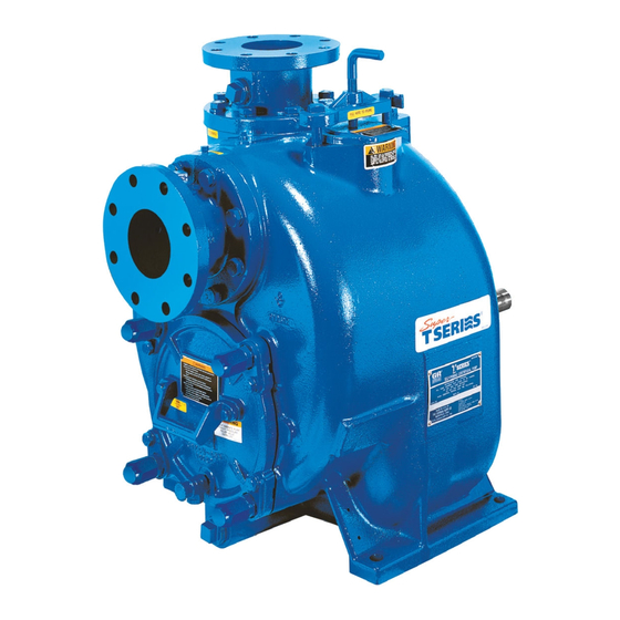
- Page 1 Rev. G 10-11-10 INSTALLATION, OPERATION, AND MAINTENANCE MANUAL WITH PARTS LIST T SERIES PUMPS MODELS T3A60-B INCLUDING: /F THE GORMAN-RUPP COMPANY D MANSFIELD, OHIO www.grpumps.com GORMAN-RUPP OF CANADA LIMITED ST. THOMAS, ONTARIO, CANADA Printed in U.S.A. 1996 The Gorman-Rupp Company...
- Page 2 Valid serial number and e-mail address required. RECORD YOUR PUMP MODEL AND SERIAL NUMBER Please record your pump model and serial number in the spaces provided below. Your Gorman-Rupp distributor needs this information when you require parts or service. Pump Model:...
-
Page 3: Table Of Contents
TABLE OF CONTENTS INTRODUCTION ..........PAGE I −... - Page 4 TABLE OF CONTENTS (continued) TROUBLESHOOTING − SECTION D ......PAGE D − 1 PREVENTIVE MAINTENANCE .
-
Page 5: Introduction
T SERIES OM−01927 INTRODUCTION Thank You for purchasing a Gorman-Rupp pump. For information or technical assistance on the Read this manual carefully to learn how to safely power source, contact the power source manufac- install and operate your pump. Failure to do so turer’s local dealer or representative. -
Page 6: Safety − Section A
OM−01927 SAFETY − SECTION A This information applies to T Series ba- 6. Vent the pump slowly and cau- sic pumps. Gorman-Rupp has no con- tiously. trol over or particular knowledge of the 7. Drain the pump. power source which will be used. Refer... - Page 7 OM−01927 T SERIES charge valve, pump components will these parts with great force when they deteriorate, and the liquid could come are disengaged. Allow the pump to to a boil, build pressure, and cause the completely cool before servicing it. pump casing to rupture or explode.
-
Page 8: Installation − Section Bpage B
See Figure 1 for the approximate physical dimen- configuration, and priming must be tailored to the sions of this pump. OUTLINE DRAWING NOTE: OPTIONAL ASA OR DIN STANDARD SUCTION & DISCHARGE SPOOL FLANGES AVAILABLE Figure 1. Pump Model T3A60-B, Including /F INSTALLATION PAGE B − 1... -
Page 9: Preinstallation Inspection
If the maximum shelf life has been exceeded, or if anything appears to be abnormal, contact your Gorman-Rupp distributor or the factory to deter- Materials mine the repair or updating policy. Do not put the pump into service until appropriate action has Either pipe or hose maybe used for suction and been taken. -
Page 10: Line Configuration
T SERIES OM−01927 compatible with the liquid being pumped. If hose is Fittings used in suction lines, it must be the rigid-wall, rein- Suction lines should be the same size as the pump forced type to prevent collapse under suction. Us- inlet. -
Page 11: Suction Line Positioning
OM−01927 T SERIES If it is necessary to position inflow close to the suc- Suction Line Positioning tion inlet, install a baffle between the inflow and the The depth of submergence of the suction line is suction inlet at a distance 1 1/2 times the diameter critical to efficient pump operation. -
Page 12: Bypass Lines
If the application involves a high discharge overall pumping efficiency. Therefore, it is recom- head, gradually close the discharge mended that a Gorman-Rupp Automatic Air Re- throttling valve before stopping the pump. lease Valve be installed in the bypass line. -
Page 13: Automatic Air Release Valve
If piping is used for the bleed line, avoid fold pipe. Contact your Gorman-Rupp distributor or the use of elbows whenever possible. the Gorman-Rupp Company for information about... -
Page 14: Alignment
Check Rotation, Section C, before final alignment of the pump. Figure 4. Aligning Spider-Type Couplings When mounted at the Gorman-Rupp factory, driver and pump are aligned before shipment. Misalign- ment will occur in transit and handling. Pumps must be checked and realigned before operation. -
Page 15: Drive Belt Tensioning
OM−01927 T SERIES tems using two or more belts, make certain that the belts are a matched set; unmatched sets will cause accelerated belt wear. Do not operate the pump without the guard in place over the rotating parts exposed rotating parts can catch cloth- ing, fingers, or tools, causing severe in- jury to personnel. -
Page 16: Operation − Section C
OM−01927 T SERIES OPERATION − SECTION C Review all SAFETY information in Section A. 1. The pump is being put into service for the first time. Follow the instructions on all tags, labels and de- 2. The pump has not been used for a consider- cals attached to the pump. -
Page 17: Operation
Lines With a Bypass Liquid Temperature And Overheating If a Gorman-Rupp Automatic Air Release Valve has The maximum liquid temperature for this pump is been installed, the valve will automatically open to 160_ F (71_ C). Do not apply it at a higher operat- allow the pump to prime, and automatically close ing temperature. -
Page 18: Strainer Check
OM−01927 T SERIES valve with a substitute which has not been speci- fied or provided by the Gorman-Rupp Company. Strainer Check If the application involves a high discharge head, gradually close the discharge If a suction strainer has been shipped with the throttling valve before stopping the pump. - Page 19 OM−01927 T SERIES against the housing. Record this temperature for AND REPAIR). Bearing overheating can also be future reference. caused by shaft misalignment and/or excessive vi- bration. A sudden increase in bearing temperature is a warning that the bearings are at the point of failing When pumps are first started, the bearings may to operate properly.
- Page 20 T SERIES OM−01927 TROUBLESHOOTING − SECTION D Review all SAFETY information in Section A. Before attempting to open or service the pump: 1. Familiarize yourself with this manual. 2. Lock out or disconnect the power source to ensure that the pump will remain inoperative.
- Page 21 OM−01927 T SERIES TROUBLE POSSIBLE CAUSE PROBABLE REMEDY PUMP STOPS OR Strainer clogged. Check strainer and clean if neces- FAILS TO DELIVER sary. RATED FLOW OR PRESSURE Suction intake not submerged at Check installation and correct sub- proper level or sump too small. mergence as needed.
- Page 22 Gorman-Rupp pump. For specific questions con- For new applications, a first inspection of wearing cerning your application, contact your Gorman- parts at 250 hours will give insight into the wear rate Rupp distributor or the Gorman-Rupp Company.
- Page 23 OM−01927 T SERIES Preventive Maintenance Schedule Service Interval* Item Daily Weekly Monthly Semi- Annually Annually General Condition (Temperature, Unusual Noises or Vibrations, Cracks, Leaks, Loose Hardware, Etc.) Pump Performance (Gauges, Speed, Flow) Bearing Lubrication Seal Lubrication (And Packing Adjustment, If So Equipped) V-Belts (If So Equipped) Air Release Valve Plunger Rod (If So Equipped) Front Impeller Clearance (Wear Plate)
- Page 24 MAINTENANCE AND REPAIR OF THE WEARING PARTS OF THE PUMP WILL MAINTAIN PEAK OPERATING PERFORMANCE. STANDARD PERFORMANCE FOR PUMP MODEL T3A60-B, Including /F Based on 70_ F (21_ C) clear water at sea level Contact the Gorman-Rupp Company to verify per- formance or part numbers.
- Page 25 OM−01927 T SERIES SECTION DRAWING PARTS PAGE Figure 1. Pump Model T3A60−B, Including /F PAGE E − 2 MAINTENANCE & REPAIR...
- Page 26 PARTS LIST Pump Model T3A60−B, Including /F (From S/N 1105021 Up) If your pump serial number is followed by an N", your pump is NOT a standard production model. Contact the Gorman-Rupp Company to verify part numbers. ITEM PART NAME PART MAT’L...
- Page 27 OM−01927 T SERIES SECTION DRAWING SEAL AREA DETAIL DRIVE END VIEW Figure 2. 44163−215 Repair Rotating Assembly PAGE E − 4 MAINTENANCE & REPAIR...
- Page 28 OM−01927 T SERIES PARTS LIST 44163−215 Repair Rotating Assembly ITEM PART NAME PART MAT’L ITEM PART NAME PART MAT’L NUMBER CODE NUMBER CODE INSTRUCTION DECAL 6588U −−− IMPELLER 11406 11010 OPTIONAL: SEAL ASSEMBLY 46513−151 −−− ADI SEAL PLATE 11837D 1102H SEAL PLATE GASKET 10959G 20000...
- Page 29 OM−01927 T SERIES PUMP AND SEAL DISASSEMBLY AND REASSEMBLY Review all SAFETY information in Section A. Use lifting and moving equipment in good repair and with adequate capacity Follow the instructions on all tags, label and decals to prevent injuries to personnel or dam- attached to the pump.
- Page 30 T SERIES OM−01927 Immobilize the impeller by wedging a block wood ing 1/2-inch pipe (schedule 80 steel or malleable between the vanes and the pump casing, and re- iron) and a standard tee (see Figure 4). All threads move the impeller capscrew and washer (24 and are 1/2-inch NPT.
- Page 31 OM−01927 T SERIES An alternate method of removing the stationary the shaft, it is recommended that bearings seal components is to remove the hardware (20 be cleaned and inspected in place. It is and 21) and separate the seal plate (22) and gas- strongly recommended that the bearings ket (3) from the bearing housing (6).
- Page 32 T SERIES OM−01927 Shaft and Bearing Reassembly and Installation ings should never be heated with a direct flame or directly on a hot plate. (Figure 2) NOTE Clean the bearing housing, shaft and all compo- If a hot oil bath is used to heat the bearings, both the nent parts (except the bearings) with a soft cloth oil and the container must be absolutely clean.
- Page 33 OM−01927 T SERIES the bearing cap with the hardware (13 and 14). Be Clean the seal cavity and shaft with a cloth soaked careful not to damage the oil seal lip on the shaft in fresh cleaning solvent. Inspect the stationary keyway.
- Page 34 T SERIES OM−01927 shaft and secure it to the bearing housing with the Continue to screw the impeller onto the shaft. This hardware (20 and 21). will press the stationary seat into the seal plate bore. To prevent damaging the shaft sleeve O-ring (19) NOTE on the shaft threads, stretch the O-ring over a piece A firm resistance will be felt as the impeller presses...
- Page 35 OM−01927 T SERIES Handle the seal parts with extreme care to prevent damage. Be careful not to contaminate precision finished faces; even fingerprints on the faces can shorten seal life. If necessary, clean the faces with a The shaft and impeller threads must be non-oil based solvent and a clean, lint-free tissue.
- Page 36 T SERIES OM−01927 Rotating Assembly Installation NOTE The check valve assembly must be replaced as a (Figure 1) complete unit. Individual parts are not sold sepa- rately. NOTE If the pump has been completely disassembled, it Reach through the back cover opening with the is recommended that the suction check valve and check valve (30), and position the check valve back cover assembly be reinstalled at this point.
- Page 37 Never Bearings replace this valve with a substitute which has not (Figure 2) been specified or provided by the Gorman-Rupp Company. The bearing housing was fully lubricated when shipped from the factory. Check the oil level regu-...
- Page 38 For U.S. and International Warranty Information, Please Visit www.grpumps.com/warranty or call: U.S.: 419−755−1280 International: +1−419−755−1352 For Canadian Warranty Information, Please Visit www.grcanada.com/warranty or call: 519−631−2870 THE GORMAN-RUPP COMPANY D MANSFIELD, OHIO GORMAN-RUPP OF CANADA LIMITED ST. THOMAS, ONTARIO, CANADA...
Need help?
Do you have a question about the T3A60-B and is the answer not in the manual?
Questions and answers