GORMAN-RUPP SUPER T Series Installation, Operation And Maintenance Manual
Hide thumbs
Also See for SUPER T Series:

Related Manuals for GORMAN-RUPP SUPER T Series


Summary of Contents for GORMAN-RUPP SUPER T Series
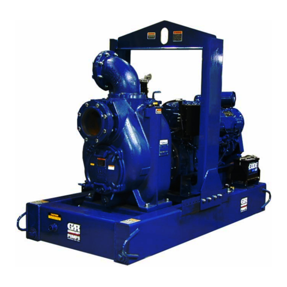
- Page 1 OM-05517-02 June 9, 2005 Rev. C 03‐27‐15 INSTALLATION, OPERATION, AND MAINTENANCE MANUAL WITH PARTS LIST SUPER T SERIESr PUMP MODEL T8A60S-F6L GORMAN‐RUPP PUMPS www.grpumps.com 2005 Gorman‐Rupp Pumps Printed in U.S.A.
- Page 2 Register your new Gorman‐Rupp pump online at www.grpumps.com Valid serial number and e‐mail address required. The engine exhaust from this product contains chemicals known to the State of California to cause cancer, birth defects or other reproductive harm. RECORD YOUR PUMP MODEL AND SERIAL NUMBER Please record your pump model and serial number in the spaces provided below.
-
Page 3: Table Of Contents
TABLE OF CONTENTS INTRODUCTION ..........PAGE I - 1 SAFETY ‐... - Page 4 TABLE OF CONTENTS (continued) Horn Delay ............PAGE C - 5 OPERATION .
-
Page 5: Introduction
SUPER T SERIES OM-05517 INTRODUCTION Thank You for purchasing a Gorman‐Rupp pump. HAZARD AND INSTRUCTION Read this manual carefully to learn how to safely DEFINITIONS install and operate your pump. Failure to do so could result in personal injury or damage to the The following are used to alert maintenance per... -
Page 6: Safety - Section A
SUPER T SERIES OM-05517 SAFETY ‐ SECTION A This information applies to Super T Se during automatic operation. Disconnect riesr engine driven pumps. Refer to the the positive battery cable before per manual accompanying the engine be forming any maintenance. Failure to do fore attempting to begin operation. - Page 7 OM-05517 SUPER T SERIES more power. The governor establishes safe operating limits that should not be exceeded. Refer to the performance curve in Section E for the maximum op Do not remove plates, covers, gauges, erating speed for this unit.
-
Page 8: Installation - Section B
SUPER T SERIES OM-05517 INSTALLATION - SECTION B Review all SAFETY information in Section A. specific application. Since the pressure supplied to the pump is critical to performance and safety, Since pump installations are seldom identical, this be sure to limit the incoming pressure to 50% of the... -
Page 9: Battery Specifications And Installation
OM-05517 SUPER T SERIES ing, check for loose hardware at mating sur Table 1. Battery Specifications faces. Cold Reserve Approx. Amp/ Crank Capacity Overall Voltage Amps Dims. @ 80 c. Carefully read all warnings and cautions con (Minutes) (Inches) Rating tained in this manual or affixed to the pump, 10.25L... -
Page 10: Mounting
SUPER T SERIES OM-05517 Mounting Line Configuration Keep suction and discharge lines as straight as Locate the pump in an accessible place as close as possible to minimize friction losses. Make mini practical to the liquid being pumped. Level mount... -
Page 11: Strainers
OM-05517 SUPER T SERIES mally used in suction lines, but if a valve is used, sump at a distance equal to 1 1/2 times the diame install it with the stem horizontal to avoid air pock ter of the suction line. -
Page 12: Float Switches
SUPER T SERIES OM-05517 Figure 2. Recommended Minimum Suction Line Submergence vs. Velocity FLOAT SWITCHES above the point where it bends along the bot tom. Direct the suction line toward the flow, and the float(s) away from the flow. If a stand... -
Page 13: Optional Submersible Transducer
OM-05517 SUPER T SERIES ENGINE (0.9) CONTROL (.76) (Emptying) (0.6) (Filling) (.46) OPERATING (0.3) RANGE CABLE (See Table Below) TETHER (.15) POINT (Emptying) (0.3) (0.6) (0.9) (1.2) APPROXIMATE FREE CORD LENGTH IN FT. (M) 1.25” Pipe (Filling) (Not Furnished) Figure 3. Float Switch Data OPTIONAL SUBMERSIBLE above the point where it bends along the bot... -
Page 14: Discharge Lines
SUPER T SERIES OM-05517 SUCTION LINE DISCHARGE LINE SIGNAL CABLE (ATTACH TO SUCTION LINE) SUCTION SUBMERSIBLE STRAINER TRANSDUCER (DOWNSTREAM FROM SUCTION) FLOW Figure 4. Typical Submersible Transducer Installation DISCHARGE LINES Siphoning If the application involves a high discharge Do not terminate the discharge line at a level lower head, gradually close the discharge than that of the liquid being pumped unless a si... -
Page 15: Automatic Air Release Valve
OM-05517 SUPER T SERIES NOTE The bypass line should be sized so that it does not affect pump discharge capacity; however, the by pass line should be at least 1 inch (25,4 mm) in di Except in certain specific applications (to ameter to minimize the chance of plugging. -
Page 16: Air Release Valve Installation
SUPER T SERIES OM-05517 per minute) will occur when the valve is fully closed. Be sure the bypass line is directed back to the wet well or tank to prevent hazardous spills. É When the pump shuts down, the spring returns the É... -
Page 17: Alignment
OM-05517 SUPER T SERIES DISCHARGE PIPE CLEAN‐OUT COVER INSTALL AIR RELEASE VALVE IN HORIZONTAL POSITION DISCHARGE CHECK VALVE 90_ LONG RADIUS ELBOW SUPPORT PUMP DISCHARGE BRACKET SELF‐PRIMING CENTRIFUGAL PUMP BLEED LINE 1” (25,4 MM) DIA. MIN. (CUSTOMER FUR NISHED) DO NOT EX... -
Page 18: Operation - Section C
OM-05517 SUPER T SERIES OPERATION - SECTION C Review all SAFETY information in Section A. cated (see LUBRICATION in MAINTENANCE AND REPAIR). Follow the instructions on all tags, labels and This pump is self‐priming, but the pump should decals attached to the pump. -
Page 19: Starting
OM-05517 SUPER T SERIES Press and hold the white “AUTO” button on the STARTING control panel until the red “AUTO” light illuminates. The auto‐start system is now armed. NOTE The unit can continue to be started manually with This pump is equipped with an automat... -
Page 20: Optional Eps Control
OM-05517 SUPER T SERIES Stop the unit manually by pressing the “OFF/SET” f) SEt b.on... B ON setpoint, units of level. button. g) Hrn dLy... Horn on, A output delay time, 5-30 seconds, in OPTIONAL EPS CONTROL 5‐second increments. h) LO BAT... -
Page 21: Eps Functions
OM-05517 SUPER T SERIES EPS Functions ter false signals that could cause “nuisance” trip ping of the contacts. Actual functions of the control occur as follows: Power is applied to the unit. NOTE If the “Hrn dLy” is changed during the actual A out... -
Page 22: Span Adjustment
OM-05517 SUPER T SERIES Press 3 times and the LCD screen will display “Calibrate Zro”. Press until a character or number on the display changes. A manual shut‐off valve should not be Press to accept the entry and advance to “Cali... - Page 23 OM-05517 SUPER T SERIES Liquid Temperature And Overheating should also be checked if pump flow rate begins to drop. If a vacuum suction gauge has been in stalled, monitor and record the readings regularly The maximum liquid temperature for this pump is to detect strainer blockage.
- Page 24 OM-05517 SUPER T SERIES vates the “Off” float switch(s) or “Off” setpoint shutdown before putting the unit back stored in the optional EPS. The pump will restart into service. Consult the factory for ad automatically when the liquid rises and activates ditional information.
- Page 25 OM-05517 SUPER T SERIES A sudden increase in bearing temperatures is a BEARING TEMPERATURE CHECK warning that the bearings are at the point of failing to operate properly. Make certain that the bearing Bearings normally run at higher than ambient tem...
- Page 26 SUPER T SERIES OM-05517 TROUBLESHOOTING - SECTION D Review all SAFETY information in Section A. 5. Close the suction and discharge valves. 6. Vent the pump slowly and cau tiously. 7. Drain the pump. Before attempting to open or service the pump: 1.
- Page 27 OM-05517 SUPER T SERIES TROUBLE POSSIBLE CAUSE PROBABLE REMEDY PUMP STOPS OR FAILS Suction intake not submerged at Check installation and correct sub TO DELIVER RATED proper level or sump too small. mergence as needed. FLOW OR PRESSURE Impeller or other wearing parts Replace worn or damaged parts.
- Page 28 SUPER T SERIES OM-05517 equipped) between regularly scheduled inspec PREVENTIVE MAINTENANCE tions can indicate problems that can be corrected Since pump applications are seldom identical, and before system damage or catastrophic failure oc pump wear is directly affected by such things as curs.
- Page 29 SUPER T SERIES OM-05517 PUMP MAINTENANCE AND REPAIR ‐ SECTION E MAINTENANCE AND REPAIR OF THE WEARING PARTS OF THE PUMP WILL MAINTAIN PEAK OPERATING PERFORMANCE. STANDARD PERFORMANCE FOR PUMP MODEL T8A60S-F6L Based on 70 F (21 C) clear water at sea level Contact the Gorman‐Rupp Company to verify per...
- Page 30 OM-05517 SUPER T SERIES ILLUSTRATION PARTS PAGE Figure 1. Pump Model T8A60S-F6L PAGE E - 2 MAINTENANCE & REPAIR...
- Page 31 SUPER T SERIES OM-05517 PARTS LIST Pump Model T8A60S-F6L (From S/N 1318431 Up) If your pump serial number is followed by an “N”, your pump is NOT a standard production model. Contact the Gorman‐Rupp Company to verify part numbers. ITEM...
- Page 32 OM-05517 SUPER T SERIES ILLUSTRATION Figure 2. Deutz Power Unit Kit PAGE E - 4 MAINTENANCE & REPAIR...
- Page 33 SUPER T SERIES OM-05517 PARTS LIST Deutz Power Unit Kit ITEM PART PART NAME NUMBER DEUTZ D914l6 ENGINE 29217-361 BASE/ FUEL TANK ASSY 41553-032 24150 LIFTING BAIL KIT 48274-801 CONTROL BOX KIT 48313-794 BATTERY BOX ASSY 4D 42432-001 ENGINE RAIL - LH...
- Page 34 OM-05517 SUPER T SERIES ILLUSTRATION Figure 3. T8A60S-(SAE 3/10) Pump End Assembly PAGE E - 6 MAINTENANCE & REPAIR...
- Page 35 SUPER T SERIES OM-05517 PARTS LIST T8A60S-(SAE 3/10) Pump End Assembly ITEM PART NAME PART ITEM PART NAME PART NUMBER NUMBER PUMP CASING SEE NOTE BELOW -DRIVE SCREW BM#04-03 17000 REPAIR ROTATING ASSY 44163-357 -FILL COVER GASKET 50G 19210 STUD...
- Page 36 OM-05517 SUPER T SERIES ILLUSTRATION Figure 4. Repair Rotating Assembly PAGE E - 8 MAINTENANCE & REPAIR...
- Page 37 SUPER T SERIES OM-05517 PARTS LIST Repair Rotating Assembly ITEM PART NAME PART ITEM PART NAME PART NUMBER NUMBER IMPELLER 12349D 11000 O‐RING S333 RETAINING RING S215 CARTRIDGE SEAL ASSY 46513-154 IMP ADJ SHIM SET 5091 17090 BALL BEARING 23422-412 SHAFT SLEEVE O‐RING...
- Page 38 OM-05517 SUPER T SERIES ILLUSTRATION 0.25 IN. 6,3 MM Figure E-5. Drive Assembly PARTS LIST ITEM PART PART NAME NUMBER COUPLING KIT 48112-015 -BUSHING 24131-497 -COUPLING ASSEMBLY 24391-104 -LOCKWASHER 21171-536 -SOCKET HD CAPSCREW BD0606-1/2 15991 -SOCKET HD CAPSCREW 22644-220 HEX HD CAPSCREW...
- Page 39 SUPER T SERIES OM-05517 PUMP AND SEAL DISASSEMBLY AND REASSEMBLY Before attempting to open or service the pump: Review all SAFETY information in Section A. 1. Familiarize yourself with this man ual. Follow the instructions on all tags, label and de...
- Page 40 OM-05517 SUPER T SERIES Remove the back cover nuts (14) and pry the back unit using the lifting eye. It is designed cover and assembled wear plate from the pump to facilitate removal or installation of in casing (1). dividual components only. Additional...
- Page 41 SUPER T SERIES OM-05517 shaft (24) with the “V” notch positioned over the Install three of the outer capscrews in the jacking shaft key. holes in the casing ring and use them to jack the rotating assembly loose from the pump casing.
- Page 42 OM-05517 SUPER T SERIES An alternate method of removing the stationary seal components is to remove the hardware (15 and 16) and separate the seal plate (5) and gasket (6) from the bearing housing (9). Position the seal To prevent damage during removal from plate on a flat surface with the impeller side down.
- Page 43 SUPER T SERIES OM-05517 er (26), and use a bearing puller to remove the oil and the container must be absolutely clean. If bearings from the shaft. the oil has been previously used, it must be thor oughly filtered. Shaft and Bearing Reassembly and Installation...
- Page 44 OM-05517 SUPER T SERIES just larger than the O.D. of the lip seal area of the Seal Installation shaft. (Figures 4, 7, 8 and 9) With the lip seal sleeve in place, lubricate the lip seal area of the shaft, and slide the shaft and as...
- Page 45 SUPER T SERIES OM-05517 SEAL PLATE SPRING RETAINER O‐RINGS IMPELLER SLEEVE O‐RING IMPELLER INTEGRAL SHIMS SHAFT SLEEVE IMPELLER STATIONARY SHAFT ROTATING ELEMENT ELEMENT SHEAR RING BELLOWS (SHEARED) SPRING OIL SEAL CENTERING WASHER STATIONARY DRIVE BAND SEAT Figure 7. Cartridge Seal Assembly as required before proceeding with seal installa...
- Page 46 OM-05517 SUPER T SERIES If necessary to reuse an old seal in an emer O‐RING ENGAGED WITH SEAL PLATE gency, carefully separate the rotating and station BORE ary seal faces from the bellows retainer and sta tionary seat. A new seal assembly should be installed any time the old seal is removed from the pump.
- Page 47 SUPER T SERIES OM-05517 Slide the rotating portion of the seal (consisting of Rotating Assembly Installation the integral shaft sleeve, spring centering washer, (Figure 3) spring, bellows and retainer, and rotating element) onto the shaft until the seal faces contact.
- Page 48 OM-05517 SUPER T SERIES Reach through the back cover opening with the USE TWO USE TWO REMAINING OPPOSING ADJUSTING SCREWS AND check valve and position the check valve adaptor BACK COVER NUTS LOCKING COLLARS TO SET FACE CLEARANCE TO PRESS in the mounting slot in the suction flange (46).
- Page 49 SUPER T SERIES OM-05517 they engage the pump casing. Install the locking This will allow the two portions of the cou collars and hardware (35 and 36). Reinstall the pling to fully engage when the drive flange back cover nuts.
- Page 50 OM-05517 SUPER T SERIES PRESSURE RELIEF VALVE LUBRICATION MAINTENANCE Seal Assembly (Figure 3) (Figure 4) The back cover is equipped with a pressure relief valve (32) to provide additional safety for the pump Before starting the pump, remove the vented plug...
- Page 51 For U.S. and International Warranty Information, Please Visit www.grpumps.com/warranty or call: U.S.: 419-755-1280 International: +1-419-755-1352 For Canadian Warranty Information, Please Visit www.grcanada.com/warranty or call: 519-631-2870 GORMAN‐RUPP PUMPS...
Need help?
Do you have a question about the SUPER T Series and is the answer not in the manual?
Questions and answers