Table of Contents
Advertisement
Quick Links
Advertisement
Table of Contents

Related Manuals for GORMAN-RUPP SUPER T8A71S-B/FM


Summary of Contents for GORMAN-RUPP SUPER T8A71S-B/FM
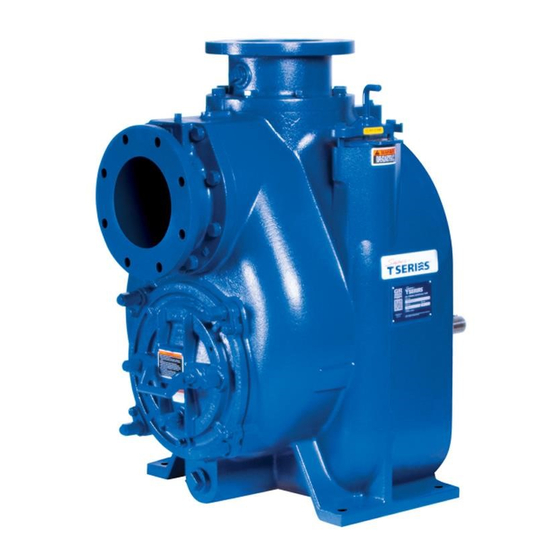
- Page 1 OM-05352-02 January 24, 2020 Rev. B - 11‐4‐22 INSTALLATION, OPERATION, AND MAINTENANCE MANUAL WITH PARTS LIST SUPER T SERIES PUMPS MODELS T8A71S-B INCLUDING: /F, /FM GORMAN‐RUPP PUMPS www.grpumps.com 2020 Gorman‐Rupp Pumps Printed in U.S.A.
- Page 2 Register your new Gorman‐Rupp pump online at www.grpumps.com Valid serial number and e‐mail address required. RECORD YOUR PUMP MODEL AND SERIAL NUMBER Please record your pump model and serial number in the spaces provided below. Your Gorman‐Rupp distributor needs this information when you require parts or service. Pump Model: Serial Number:...
-
Page 3: Table Of Contents
TABLE OF CONTENTS INTRODUCTION ..........PAGE I - 1 SAFETY - SECTION A . - Page 4 TABLE OF CONTENTS (continued) BEARING TEMPERATURE CHECK ......... . PAGE C - 4 TROUBLESHOOTING - SECTION D .
-
Page 5: Introduction
SUPER T SERIES OM-05352 INTRODUCTION Thank You for purchasing a Gorman‐Rupp pump. HAZARD AND INSTRUCTION Read this manual carefully to learn how to safely DEFINITIONS install and operate your pump. Failure to do so could result in personal injury or damage to the The following are used to alert maintenance per... -
Page 6: Safety - Section A
SUPER T SERIES OM-05352 SAFETY - SECTION A This information applies to Super T Se riesr basic pumps. Gorman‐Rupp has no control over or particular knowledge of the power source which will be used. This pump is designed to handle liquids Refer to the manual accompanying the containing large entrained solids or power source before attempting to be... - Page 7 OM-05352 SUPER T SERIES Do not operate the pump against a Do not operate the pump without the closed discharge valve for long periods of time. If operated against a closed dis guards in place over the rotating parts. charge valve, pump components will Exposed rotating parts can catch cloth...
-
Page 8: Installation - Section B
SUPER T SERIES OM-05352 INSTALLATION - SECTION B Review all SAFETY information in Section A. specific application. Since the pressure supplied to the pump is critical to performance and safety, Since pump installations are seldom identical, this be sure to limit the incoming pressure to 50% of section offers only general recommendations and the maximum permissible operating pressure as practices required to inspect, position, and ar... -
Page 9: Preinstallation Inspection
OM-05352 SUPER T SERIES PREINSTALLATION INSPECTION POSITIONING PUMP The pump assembly was inspected and tested be fore shipment from the factory. Before installation, inspect the pump for damage which may have oc Death or serious personal injury and curred during shipment. Check as follows: damage to the pump or components can occur if proper lifting procedures a. -
Page 10: Suction And Discharge Piping
SUPER T SERIES OM-05352 suction and discharge ports and install the lines. SUCTION AND DISCHARGE PIPING Installation closer to the pump may result in erratic readings. Pump performance is adversely effected by in SUCTION LINES creased suction lift, discharge elevation, and fric tion losses. -
Page 11: Suction Lines In Sumps
OM-05352 SUPER T SERIES Suction Lines In Sumps of one or both pumps. To avoid this, position the suction inlets so that they are separated by a dis If a single suction line is installed in a sump, it tance equal to at least 3 times the diameter of the should be positioned away from the wall of the suction pipe. -
Page 12: Discharge Lines
SUPER T SERIES OM-05352 minimize the chance of plugging. DISCHARGE LINES Siphoning In low discharge head applications (less than 30 feet or 9 meters), it is recommended that the by Do not terminate the discharge line at a level lower pass line be run back to the wet well, and located 6 than that of the liquid being pumped unless a si... -
Page 13: Automatic Air Release Valve
OM-05352 SUPER T SERIES AUTOMATIC AIR RELEASE VALVE When properly installed, a Gorman‐Rupp Auto matic Air Release Valve will permit air to escape If a manual shut‐off valve is installed in through the bypass line and then close automati a bypass line, it must not be left closed cally when the pump is fully primed and pumping during operation. -
Page 14: Alignment
SUPER T SERIES OM-05352 DISCHARGE PIPE CLEAN‐OUT COVER INSTALL AIR RELEASE VALVE IN HORIZONTAL POSITION DISCHARGE CHECK VALVE 90_ LONG RADIUS ELBOW SUPPORT PUMP DISCHARGE BRACKET SELF‐PRIMING CENTRIFUGAL PUMP BLEED LINE 1” (25,4 MM) DIA. MIN. (CUSTOMER FUR NISHED) DO NOT EX SUCTION TEND BELOW PUMP LINE... -
Page 15: Coupled Drives
OM-05352 SUPER T SERIES Adjusting the alignment in one direction may alter the alignment in another direc tion. check each procedure after altering alignment. Coupled Drives Figure 5. Aligning Non‐Spider Type Couplings Check parallel adjustment by laying a straightedge across both coupling rims at the top, bottom, and When using couplings, the axis of the power side. -
Page 16: Drive Belt Tensioning
SUPER T SERIES OM-05352 Select pulleys that will match the proper speed ra DRIVE BELT TENSIONING tio; overspeeding the pump may damage both General Rules of Tensioning pump and power source. For new drive belts, check the tension after 5, 20 and 50 hours of operation and re‐tension as re... -
Page 17: Operation - Section C
OM-05352 SUPER T SERIES OPERATION - SECTION C Review all SAFETY information in Section A. 2. The pump has not been used for a consider able length of time. Follow the instructions on all tags, labels and de 3. The liquid in the pump casing has evapo cals attached to the pump. -
Page 18: Operation
OM-05352 SUPER T SERIES Consult the operating manual furnished with the filled, adjust the throttling valve to the required flow power source before attempting to start the power rate. source. If an electric motor is used to drive the pump, re move V‐belts, couplings, or otherwise disconnect the pump from the motor before checking motor Do not operate the pump against a... -
Page 19: Strainer Check
OM-05352 SUPER T SERIES gaged to be ejected with great force. Af 2. Disconnect or lock out the power ter the pump completely cools, drain the source to ensure that the pump will liquid from the pump by removing the remain inoperative. -
Page 20: Cold Weather Preservation
OM-05352 SUPER T SERIES shock waves can be transmitted to the pump and remaining liquid that could freeze the pump rotat piping system. Close all connecting valves slowly. ing parts. If the pump will be idle for more than a few hours, or if it has been pumping liquids con... - Page 21 SUPER T SERIES OM-05352 TROUBLESHOOTING - SECTION D Review all SAFETY information in Section A. Before attempting to open or service the pump: 1. Familiarize yourself with this manual. 2. Lock out or disconnect the power source to ensure that the pump will remain inoperative.
- Page 22 OM-05352 SUPER T SERIES TROUBLE POSSIBLE CAUSE PROBABLE REMEDY Suction intake not submerged at Check installation and correct PUMP STOPS OR FAILS TO DELIVER proper level or sump too small. submergence as needed. RATED FLOW OR Impeller or other wearing parts worn Replace worn or damaged parts.
- Page 23 SUPER T SERIES OM-05352 equipped) between regularly scheduled inspec PREVENTIVE MAINTENANCE tions can indicate problems that can be corrected Since pump applications are seldom identical, and before system damage or catastrophic failure oc pump wear is directly affected by such things as curs.
- Page 24 OM-05352 SUPER T SERIES PUMP MAINTENANCE AND REPAIR - SECTION E MAINTENANCE AND REPAIR OF THE WEARING PARTS OF THE PUMP WILL MAINTAIN PEAK OPERATING PERFORMANCE. STANDARD PERFORMANCE FOR PUMP MODEL T8A71S‐B, Including /F, /FM Based on 70 F (21 C) clear water at sea level Contact the Gorman‐Rupp Company to verify per...
- Page 25 OM-05352 SUPER T SERIES ILLUSTRATION PARTS PAGE 10 39 Figure 1. Pump Model T8A71S-B ncluding /F, /FM PAGE E - 2 MAINTENANCE & REPAIR...
- Page 26 OM-05352 SUPER T SERIES PARTS LIST Pump Model T8A71S-B ncluding /F, /FM (From S/N 1716886 Up) If your pump serial number is followed by an “N”, your pump is NOT a standard production model. Contact the Gorman‐Rupp Company to verify part numbers. ITEM PART NAME PART...
- Page 27 OM-05352 SUPER T SERIES ILLUSTRATION Ï Ï Ï Ï Ï Ï Î Î Î Î Ï Ï Ï Ï Ì Ì Ì Ì Î Î Î Î Î Î Ì Ì Ì Ì Î Î Î Î Î Î Î Î Î Î...
- Page 28 OM-05352 SUPER T SERIES PARTS LIST Repair Rotating Assembly ITEM PART PART NAME NUMBER IMPELLER 12349 1102H ADJ SHIM SET 5091 17090 SEAL ASSY 46513-154 SEAL PLATE 12350 1102H GASKET 12350G 20000 OIL SEAL S1917 PIPE PLUG P04 15079 LOCK WASHER J10 15991 HEX HEAD CAP SCREW B1006 15991...
- Page 29 OM-05352 SUPER T SERIES For power source disassembly and repair, consult PUMP AND SEAL DISASSEMBLY the literature supplied with the power source, or AND REASSEMBLY contact your local power source representative. Review all SAFETY information in Section A. Follow the instructions on all tags, label and decals Before attempting to open or service the attached to the pump.
- Page 30 Inspect the back cover O‐rings (6 and 7) and re place it if damaged or worn. Suction Check Valve Removal Use Only Genuine Gorman-Rupp re (Figure 1) placement parts. Failure to do so may cre ate a hazard and damage the pump or di...
- Page 31 OM-05352 SUPER T SERIES bly has been removed from the pump casing. screws in the jacking holes in the casing ring and use them to press the rotating assembly into the pump casing until the bearing housing is free. Turn Remove the jacking screws from the casing ring.
- Page 32 SUPER T SERIES OM-05352 Seal Removal Pry or press the oil seals (6) from the bearing hous ing. (Figure 2) After removing the shaft and bearings, clean and Slide the shaft sleeve and rotating portion of the inspect the bearings in place as follows. seal off the shaft as a unit.
- Page 33 OM-05352 SUPER T SERIES housing. Replace the bearings, shaft, or bearing housing if the proper bearing fit is not achieved. If bearing replacement is required, remove the out board bearing retaining ring (20) and use a bearing To prevent damage during removal from puller to remove the bearings from the shaft.
- Page 34 SUPER T SERIES OM-05352 After the bearings have been installed and allowed Press the oil seal (6) into the bearing cap (18) with to cool, check to ensure that they have not moved the lip positioned as shown in Figure 2. Replace away from the shaft shoulders in shrinking.
- Page 35 OM-05352 SUPER T SERIES If a replacement seal is being used, remove it from sleeve O‐ring and the external stationary seat O‐ the container and inspect the precision finished ring with a very small amount of “P-80 Emul faces to ensure that they are free of any foreign sion”...
- Page 36 SUPER T SERIES OM-05352 proper clearance as described in Impeller Instal O‐RING ENGAGED WITH SEAL PLATE lation and Adjustment. BORE If necessary to reuse an old seal in an emer gency, carefully separate the rotating and station ary seal faces from the bellows retainer and sta tionary seat.
- Page 37 OM-05352 SUPER T SERIES Slide the rotating portion of the seal (consisting of Proceed with Rotating Assembly Installation be the integral shaft sleeve, spring centering washer, fore installing the impeller capscrew and washer spring, bellows and retainer, and rotating element) (26 and 27).
- Page 38 SUPER T SERIES OM-05352 in the mounting slot in the suction flange (22). Align Clean any scale or debris from the contacting sur the adaptor with the flange hole, and secure the as faces in the pump casing that might interfere or sembly with the check valve pin (27).
- Page 39 OM-05352 SUPER T SERIES back cover. Remove the rotating assembly adjust Remove the fill cover assembly (34) and fill the ing shims, then reinstall the hardware securing the pump casing with clean liquid. Reinstall the fill rotating assembly to the pump casing. Perform the cover and tighten it.
- Page 40 For Warranty Information, Please Visit www.grpumps.com/warranty or call: U.S.: 419-755-1280 Canada: 519-631-2870 International: +1-419-755-1352 GORMAN‐RUPP PUMPS...
Need help?
Do you have a question about the SUPER T8A71S-B/FM and is the answer not in the manual?
Questions and answers