TCS SuperSTAT Series Installation Manual
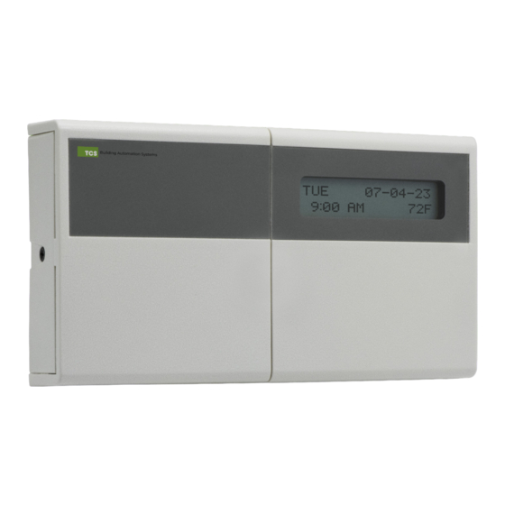
Communicating thermostat
Hide thumbs
Also See for SuperSTAT Series:
- Configuration manual (13 pages) ,
- Installation manual (7 pages)

Subscribe to Our Youtube Channel
Related Manuals for TCS SuperSTAT Series


Summary of Contents for TCS SuperSTAT Series
- Page 1 INSTALLATION MANUAL Communicating Thermostat SZ1051, SZ1053 2800 Laura Lane • Middleton, WI 53562 800.288.9383 www.tcsbasys.com 202307...
- Page 2 Contents Introduction ............................3 Opening the SuperSTAT ........................3 Mounting the SuperSTAT ........................3 Powering the SuperSTAT ........................3 SuperSTAT Wiring Connections ......................4 Power ....................................5 RS-485 Port ..................................5 Packaged Unit Terminations ............................6 Time Clock Output ................................6 Analog Outputs ................................6 Temperature Inputs .................................
- Page 3 If you have any questions regarding your SuperSTAT, do not hesitate to contact TCS Technical Support at 800.288.9383, ext. 2. Our Technical Support Department hours are Monday – Friday, 7:00 a.m. to 7:00 p.m. (CST).
- Page 4 Installation SuperSTAT Wiring Connections The input/output terminals on the SuperSTAT utilize de-pluggable terminal blocks, with two, three, or four poles. Refer to the diagram of the base below, which indicates which terminations are active. NOTE: For ease of installation, you can remove the cover from the base by unplugging the ribbon connector. Plug the connector back into its socket before final assembly.
- Page 5 Connect the power source using 18AWG two-wire twisted, stranded copper wire. NOTE: Do not connect to 120VAC. When multiple TCS/Basys Controls devices are using a single transformer, be sure to maintain the polarity of the power wiring. All TCS devices are half-wave rectified and have common return paths.
- Page 6 Installation HVAC Unit Terminations HVAC unit signals may be up to 28VAC from the equipment terminations. R W/Y1 W/Y2 G R W/Y1 W/Y2 G A02 A01 – DI3 OVR T1 Time Clock Output The Time Clock Output is an unpowered, isolated pair of relay contacts. Connect an external device that operates with a schedule based on room occupancy, such as an outdoor air damper, exhaust fan, or a dehumidification/reheat unit.
- Page 7 Installation Temperature Inputs Connect 1000Ω PtRTD temperature sensor inputs (range of –40ºF to 160ºF) using 18AWG two-wire twisted, stranded shielded wire, maximum 250 ft. length. Sensors can be used for remote zone temperature, return air temperature, discharge air temperature, or outside air temperature. Sensor wires should be kept at least five feet from live voltage wiring.
Need help?
Do you have a question about the SuperSTAT Series and is the answer not in the manual?
Questions and answers