TCS UbiquiSTAT US4010 Product Manual
Commercial bacnet thermostat
Hide thumbs
Also See for UbiquiSTAT US4010:
- Product manual (50 pages) ,
- Configuration manual (22 pages) ,
- Installation manual (8 pages)
Table of Contents
Advertisement
Quick Links
UbiquiSTAT
Commercial BACnet Thermostat
Models:
US4010/US4110 -
Single-Stage RTU / Zoning Thermostat
US4020/US4120 -
Multi-Stage RTU Thermostat
US4040/US4140 -
Advanced RTU Thermostat
US4050/US4150 -
Advanced Application Thermostat
2800 Laura Ln, Middleton WI 53562 | 800.288.9383 Fax: 608.836.9044 | www.tcsbasys.com
TM
Mon Jun 7, 2021 09:20AM
|
PRODUCT MANUAL
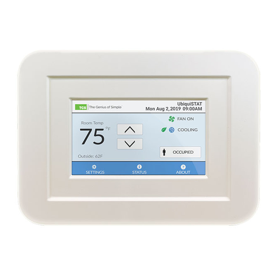
The UbiqiSTAT is a feature rich, multifunction
touchscreen thermostat which provides for
control of a wide range of HVAC applications.
This series provides a large color display, with
simple to understand control of conventional
and heat pump equipment as well as modu-
lating operation.
BACnet® is a registered
trademark of ASHRAE.
v.2106
Advertisement
Table of Contents
Troubleshooting

Subscribe to Our Youtube Channel
Related Manuals for TCS UbiquiSTAT US4010


Summary of Contents for TCS UbiquiSTAT US4010
- Page 1 PRODUCT MANUAL UbiquiSTAT The UbiqiSTAT is a feature rich, multifunction touchscreen thermostat which provides for control of a wide range of HVAC applications. This series provides a large color display, with Commercial BACnet Thermostat simple to understand control of conventional and heat pump equipment as well as modu- lating operation.
-
Page 2: Table Of Contents
7 Using TCS Insight with the UbiquiSTAT ........ -
Page 3: Features
⸰ Optional access code locks out on-screen programming ⸰ 5 Heat/Cool setpoint groups • Outdoor air heating and cooling lockouts • Includes all TCS SZ Series thermostat features • Discharge air protection limits ⸰ Includes many additional features and enhancements • Fahrenheit or Celsius temperature display •... -
Page 4: Applications
(specific to UbiquiSTAT model). It contains many standard features from the TCS SZ series thermostats, as well as enhancements and new features. The UbiquiSTAT provides two network- ing options: TCSbus and BACnet. -
Page 5: Mounting And Assembly
MOUNTING AND ASSEMBLY 1 Mounting and Assembly The UbiquiSTAT™ is designed for wall mounting using two #6 sheet metal screws, either over a 2"x4" or 4"x4" junction box, or directly to the wall. For best results, the thermostat should be mounted on an interior wall that represents a normal room environment, at a height of approximately 48"... -
Page 6: Wiring
Caution: When multiple TCS Basys Controls devices are using a single transformer, the polarity of the power wir- ing must be maintained or damage will occur. All TCS devices are half-wave rectified and have common return paths. - Page 7 WIRING DIAGRAM (US4050) US4050/US4150 Figure 1a For communication wiring, use 3-con- For sensor input wiring, use 2-conductor, ductor, twisted/shielded 22 AWG. twisted/shielded 18 AWG. Control signals may be up to nominal GND terminal is used for self powered 28 VAC from equipment transformer. 4-20mA inputs and outputs.
- Page 8 WIRING DIAGRAM (US4040) US4040/US4140 Figure 1b For communication wiring, use 3-con- GND terminal is used for self powered ductor, twisted/shielded 22 AWG. 4-20mA inputs and outputs. 4-20mA transmitter, sensor input wiring 18 Control signals may be up to nominal AWG, twisted, shielded pair. AI1 is shown as 28 VAC from equipment transformer.
- Page 9 WIRING DIAGRAM (US4020) US4020/US4120 Figure 1c For communication wiring, use 3-con- Dry contact. Must not be powered. ductor, twisted/shielded 22 AWG. Control signals may be up to nominal For sensor input wiring, use 2-conductor, 28 VAC from equipment transformer. twisted/shielded 18 AWG. 24 VAC transformer.
- Page 10 WIRING DIAGRAM (US4010) US4010/US4110 Figure 1d Packaged Unit Terminations Zone Timeclock Damper CHWV Output Y1/W2 Optional 500ohm resistor (included) REF B A R W1 G B/O TC AO1 AO2 GND A B REF DI1 DI2 DI3 GND +P AI1 AI2 GND Space/Return/ Discharge Air Outside Air...
-
Page 11: Initial Setup
BACnet Explorer Guide for a list of all BACnet objects). TCS does not supply a BACnet configuration tool at this time, but any BACnet con- figuration tool an installer has access to can also be used to program the UbiquiSTAT. -
Page 12: Digital Outputs (Do)
INITIAL SETUP These inputs must be configured using the corresponding mode objects in the internal BACnet explorer screen. See Sec- tion 4.5.2.6 for more information on the internal BACnet explorer screen. For an explanation of the features listed above, Section 3.5 Digital Outputs (DO) The various control outputs required by heat and cool stage control are mapped to physical terminal blocks on the con- troller via mechanical relays. -
Page 13: Analog Outputs (Ao)
• System Mode • Occupied Fan Mode • Communication Mode: TCSbus allows the UbiquiSTAT to reside on a network with TCS controllers. TCSbus mode re- quires a software upgrade of the Ubiquity Site Gateway. - US4100: TCSbus, BACnet MS/TP, BACnet/IP, None - US4000: TCSbus, BACnet MS/TP, None •... -
Page 14: User Interface
• Device Instance: This number must be unique across the entire BACnet network. The initial value shown is a combina- tion of the TCS BACnet vendor ID (496) and the previously entered network address. This is done in an attempt to create a unique value. -
Page 15: Status Screens
USER INTERFACE Idle : Neither heating nor cooling is active. Warning : Heating or cooling lockout in effect. See Section 5 for more information on this feature. Disabled : The control is currently disabled and not heating or cooling. This is typically shown on startup during the power on delay, or when fan proving has failed. - Page 16 USER INTERFACE 4.2.1 System Status Figure 5 System Status screen details vary pending on model-specific features. Information on the system status screen is broken into three groups: • System (top) - State: The current system state. This is the same as the system state shown on the home screen. - Schedule: The currently active setpoint pair.
- Page 17 USER INTERFACE Figure 6 Low Limit Relay State Disabled Changeover (Heat Network Override Pump Compressors) Indicator Light Not Lit Hidden Not Lit Same as On/Off Text “ON” “OFF” “--” (Protect) “(ON!)” / “(OFF!)” 4.2.2 Advanced Status Figure 7 Operating Modes Advanced Status screen details vary pending on model specific features.
- Page 18 USER INTERFACE 4.2.3 Network Status Figure 8a - RS-485 Figure 8b - Wi-Fi Information on the advanced status screen is broken into four groups: • RS-485 Settings: - Mode: This indicates the programmed network mode (TCSbus or BACnet MS/TP). - Device ID: The programmed device instance number. Device instance numbers are specific to BACnet MS/TP and are not used in the TCSbus protocol.
-
Page 19: Service Status
Service Status is defined as a state of the controller or HVAC equipment that requires action by the end user to resolve. When a service status is active, a red badge is visible on the top of the home screen to the right of the TCS logo. Touching this badge presents the service status viewer, which shows all active service statuses and when they were detected. - Page 20 (30) entries. Select new and choose month, day and year for a single occurrence where the system will revet to the unoccupied mode. Different from SZ Series Thermostats: Schedules no longer start and stop as they did on TCS SZ thermostats. Schedules now only transition from schedule to schedule.
- Page 21 USER INTERFACE 8:00 AM Monday: System changes to Occupied A schedule, which uses the A heating and cooling setpoints. 5:00 PM Monday: System changes to Unoccupied schedule which uses the Unoccupied heating and cooling setpoints. Saturday and Sunday: The Unoccupied setpoints are in effect for the entire day. Setpoint Change Example: This schedule represents a business that opens at 10:00 AM and closes at 9:00 PM weekdays, and closes at 8:00 PM on weekends.
- Page 22 - Device Instance Number (BACnet MS/TP Only): This number must be unique across the entire BACnet network. The default value is a combination of the TCS BACnet vendor Id (496) and the previously entered network address. This is 2800 Laura Ln, Middleton WI 53562 | 800.288.9383 Fax: 608.836.9044 | www.tcsbasys.com...
- Page 23 USER INTERFACE done in an attempt to create a unique value. However, users are encouraged to create their own numbering system for all controllers on the BACnet network. • BACnet Wi-Fi - Enable/Disable: Turn on and off Wi-Fi communication and related BACnet/IP features. - Scan Wi-Fi Networks: Starts a scan for available networks.
- Page 24 The system event log contains entries for the last 100 events. An event can be one of three classes: info, action, and fault. Events contain a timestamp, description, and possibly an internal programming code (meaningful only to TCS technical support). Additional information is displayed for certain events as available.
- Page 25 The access code consists of four digits; the access code “0000” disables the access code feature. If you have lost or forgotten your code, call TCS Technical Support. 2800 Laura Ln, Middleton WI 53562 | 800.288.9383 Fax: 608.836.9044 | www.tcsbasys.com...
-
Page 26: Advanced Feature Summary
ADVANCED FEATURE SUMMARY 4.5.2.12 Expert Settings By default, the UbiquiSTAT ships with two stages of heat and two stages of cool enabled (based on model feature avail- ability). Each stage may be independently disabled in order to prevent it from being considered by the control logic. This can be useful if, for example, the connected equipment does not support the stages, or to correct for a wiring error. -
Page 27: Checkout And Troubleshooting
CHECKOUT AND TROUBLESHOOTING • Fan Proving: The Fan Proving feature allows the controller to safely shut down the system in the case where the fan fails to operate correctly, avoiding damage to the heating or cooling units. The input to this feature is an external sensor that is connected to a Digital Input (DI) indicating that the fan is operating (closed) or not (open). -
Page 28: Troubleshooting
CHECKOUT AND TROUBLESHOOTING 6.2 Troubleshooting 6.2.1 No Display Remove cover and check for 24 VAC (22.8 to 27.6 VAC) on terminals labeled “+/- 24V”. Replace the cover and check for proper fit. Ensure the two internal board connectors snap in place. For more information on removing the cover, see Sec- tion 6.2.2 Fan Does Not Come On... -
Page 29: Using Tcs Insight With The Ubiquistat
Normally Closed. This causes the state of the relay to be closed (energized) when the status is “Off” and open (de-energized) when the status is “On”. The polarity can be changed using Ubiquity Cloud, TCS Insight or a third party BACnet configuration tool. -
Page 30: Schedules And Holidays (And Bacnet)
Note: This method may be used to program all thermostats on a single network simultaneously. First, connect PC/laptop to the USB-to-RS-485 serial converter (TCS QD1010). Then wire the RS-485 network on the serial converter to the network on the UbiquiSTAT. The Communication Mode must be set to “TCSbus” on the UbiquiSTAT. The chosen baud rate in Insight must match the RS-485 network settings on the UbiquiSTAT. -
Page 31: Backup/Restore
USING INSIGHT WITH UBIQUISTAT STATs with earlier firmware may also be upgraded, but must be done so using third party BACnet tools. Call TCS techni- cal support for more information. • Firmware may be “downgraded” by choosing an earlier firmware version, but there is a risk of losing all programming, depending on the compatibility of the two versions. -
Page 32: Regulatory Information
REGULATORY INFORMATION 8 Regulatory Information FCC Compliance Statement (Part 15.19) This device complies with part 15 of the FCC Rules. Operation is subject to the following two conditions: 1. This device may not cause harmful interference. 2. This device must accept any interference received, including interference that may cause undesired operation. FCC Interference Statement (Part 15.105 (b)) This equipment has been tested and found to comply with the limits for a Class B digital device, pursuant to part 15 of the FCC Rules.
Need help?
Do you have a question about the UbiquiSTAT US4010 and is the answer not in the manual?
Questions and answers