TCS SuperSTAT Series Installation Manual
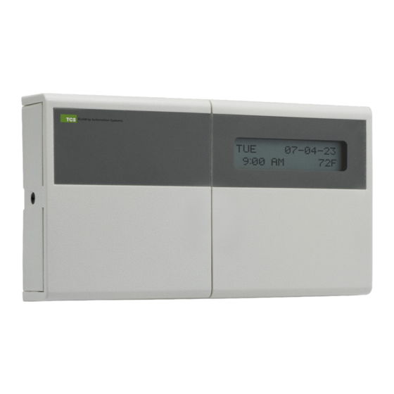
Communicating thermostat
Hide thumbs
Also See for SuperSTAT Series:
- Configuration manual (13 pages) ,
- Installation manual (7 pages)

Subscribe to Our Youtube Channel
Related Manuals for TCS SuperSTAT Series


Summary of Contents for TCS SuperSTAT Series
- Page 1 INSTALLATION MANUAL Communicating Thermostat SZ1041 2800 Laura Lane • Middleton, WI 53562 800.288.9383 www.tcsbasys.com 202307...
- Page 2 Contents Introduction ............................3 Opening the SuperSTAT ........................3 Mounting the SuperSTAT ........................3 Powering the SuperSTAT ........................3 SuperSTAT Wiring Connections ......................4 Power ....................................5 RS-485 Port ..................................5 HVAC Unit Terminations ..............................6 Analog Outputs ................................6 Temperature Inputs ................................. 6 Digital Inputs ..................................7 2800 Laura Lane •...
- Page 3 If you have any questions regarding your SuperSTAT, do not hesitate to contact TCS Technical Support at 800.288.9383, ext. 2. Our Technical Support Department hours are Monday – Friday, 7:00 a.m. to 7:00 p.m. (CST).
- Page 4 Installation SuperSTAT Wiring Connections The input/output terminals on the SuperSTAT utilize de-pluggable terminal blocks, with two, three, or four poles. Refer to the diagram of the base below, which indicates which terminations are active. NOTE: For ease of installation, you can remove the cover from the base by unplugging the ribbon connector. Plug the connector back into its socket before final assembly.
- Page 5 Connect the power source using 18AWG two-wire twisted, stranded copper wire. NOTE: Do not connect to 120VAC. When multiple TCS/Basys Controls devices are using a single transformer, be sure to maintain the polarity of the power wiring. All TCS devices are half-wave rectified and have common return paths.
- Page 6 Installation HVAC Unit Terminations HVAC unit signals may be up to 28VAC from the equipment terminations. W1 W2 W1 W2 A02 A01 – DI3 OVR T1 R W1 W2 Analog Outputs Connect 4 – 20mA, analog output devices using 18 – 22AWG two-wire twisted, stranded shielded or unshielded wire. Connected actuators, motors, or drives must be powered separately from the SuperSTAT.
- Page 7 Installation Digital Inputs Digital inputs are used to receive status signals such as filter status, fan status, etc. Use unpowered dry contacts only with 18AWG two-wire twisted, stranded shielded or unshielded wire. W1 W2 A02 A01 – DI3 OVR T1 DI1 DI2 DI3 OVR T1 2800 Laura Lane...
Need help?
Do you have a question about the SuperSTAT Series and is the answer not in the manual?
Questions and answers