Advertisement
Quick Links
ANUAL CHANGES
April 21, 1980
HANGE DATE:
MANUAL DES RIPTION
INSTRU ENT:
SERIAL PREFIX:
1,2,3,4, 5,6,7,8
1816A
1908 A
A5 Series 1916
1840A
.2
A5 Series 1840
1936 A
3
1 thru 11
1940 A
A2 Series 1848
4
1 thru 12
1948A
1852A
1 thru 13
2002A
1904 A
A5 Series 1904
3.7
5061A-1
5061 A-2
5061 A-3
5061 A-4
5061 A-6
5061 A-7
5061 A-8
OTE — THE FOLLOWI G ERRATA APPLIES O LY TO I STRUME TS WITH SERIAL PREFIX
UMBER 1740A.
17R/S/T/U — 7859-7860-7865/7883/8878/8877/7894/7893/8897-8901/8942/8926-9825/9652/9669/E/
DATE PRINTED:
HP PART NO:
ICROFICHE NO:
IF YOUR INSTRU ENT
HAS SERIAL PREFIX
OR SERIAL NU BER
JUN 1978
05061-9052
05061-9053
AKE THE
FOLLOWING CHANGES
TO YOUR
ANUAL
(This change supersedes all earlier dated
changes)
•
ake all changes listed as ERRATA.
©
Check the following table for your
instrument ' s serial prefix or serial number
and make listed change(s) to manual.
AKE THE
FOLLOWING CHANGES
TO YOUR ANUAL
HEWLETT
PA KARD
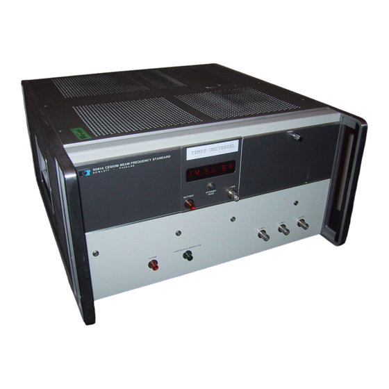
5061A Cesium Beam Frequency
Standard Operating and Service
anual
1740 A
□ NEW OR REVISED ITEM
The following Service Notes are available from your local HP Sales and Service Office.
Service Note No.
1.2,3, 4,5
1.2,3,4,5,6
Description
Improve Decade Divider IC4 in Synthesizer A1
Preferred Replacement Parts that Increase Reliability
Cesium Oven Controller Circuit
odification
Increasing Reliability and Tunability of Harmonic Generator Assembly (A4)
Installation of Hot Wire Ionizer Current Limit Resistors
Summary of Important Circuit Changes, Procedures and Replacement Parts
odification for Improved Short Term Stability
3, thru 7
1 thru 10
IF YOUR INSTRU ENT
HAS SERIAL PREFIX
OR SERIAL NU BER
ERRATA
Page 8-5, Figure 8-5, Wiring Diagram:
Add " (Serial Prefix 1816Ai " to caption.
Page 8-35, Figure 8-20, A9 Schematic Diagram:
Change SERIES numbers for A9 and A9A1 to 1816.
Page 8-55, Figure 8-30, A17 Schematic Diagram:
Add " (SERIES 17401 " to A17 description on bottom edge of diagram.
Page 8-5, Figure 8-5, Wiring Diagram:
Replace with attached Figure 1 Signal Wiring Diagram (Serial Prefix 1740A).
Page 8-35, Figure 8-20, A9 Schematic Diagram:
Replace with attached Figure 2. A9 (05061-6134 SERIES 1740) Schematic Diagram.
Page 8-55, Figure 8-30, A17 Schematic Diagram:
Change output from terminal 4 to " TO S2B (4, 6, 11,12)
ODE " .
Changeout put from terminal 22 to " TO SB2 (2, 3)
ODE " .
Advertisement


Need help?
Do you have a question about the 5061A and is the answer not in the manual?
Questions and answers