Sign In
Upload
Manuals
Brands
HP Manuals
Measuring Instruments
5340A
HP 5340A Manuals
Manuals and User Guides for HP 5340A. We have
2
HP 5340A manuals available for free PDF download: Operating And Service Manual, Calibration Procedure
HP 5340A Operating And Service Manual (279 pages)
FREQUENCY COUNTER
Brand:
HP
| Category:
Cash Counter
| Size: 14.8 MB
Table of Contents
Table of Contents
4
Model 5340A Frequency Counter. Rack Mount
12
General Information
13
Descripton
13
Instrument Identification
13
Applications
13
Options
13
Equipment Supplied and Accessories Available
13
Equipment Supplied
14
Accessories Available
14
I1 Installation and Remote Programming
18
Introduction
18
Unpacking and Inspection
18
Installation Requirements
18
Repacking for Shipment
19
Environment During Storage and Shipment
19
Remote Programming and Digital Output
19
What Can be Programmed
19
Bus Description
20
Relation of ATN and the Handshake Lines (RFD. DAC. DAV)
22
Data Transfer
23
Handshake Timing
23
Addressing the 5340A
24
Talk and Listen Addresses
25
Example of Setting an Address
26
Line Characteristics
26
Hardware
28
Programmingthe 5340A
28
5340A Rear Panel
28
5340A Digital Input/Output
29
5340A Program Code Set
30
What Is Outputted
32
Modes of Operation
32
5340A Output Code Set
32
Starting a Measurement Procedure
34
Examples of Programming
35
5340A Programming Example
36
Example Program Card
37
Operation
38
Introduction
38
Operating Characteristics
38
Operating Ranges
38
Resolution and Blanking
38
Sample Rate, Measurement Time, and Reset
39
AM Characteristics
39
FM Characteristics
39
Auto-Amplitude Discrimination
40
Maximum Input Signal Power
40
DBM to Volts Conversion
40
Input Cable Considerations
41
Controls, Indicators, and Connectors
41
Operating Procedures
41
Front Panel Controls and Indicators
43
5340A Operating Procedures
45
Self Check and Operational Check Procedures
46
Theory of Operation
48
Introduction
48
Logic Elements
48
Logic Comparison Diagrams
48
Gate Symbols
49
5340A Integrated Circuits Theory of Operation
50
And 1816-0185
50
Decade Counter 1820-0055
51
Example ROM Programming for the Equation
51
J-K Flip-Flop 1820-0065
52
Decade Counter 1820-0055
52
Dual D-Type Edge-Triggered Flip-Flop 1820-0077
53
Monostable Multivibrator 1820-0207
53
Four-Bit Binary Counter 1820-0099
54
Monostable Multivibrator 1820-0207
54
Four-Line to Ten-Line Decoder 1820-0214
55
Operational Amplifier 1820-0216
55
Monostable Multivibrator 1820-0261
56
Differential Videoamplifier 1820-0270
56
Differential Video Amplifier 1820-0270
56
Eight-Bit Serial-In Parallel-Out Shift Register 1820-0294
57
BCD to Decimal Decoder 1820-0426
57
Voltage Comparator/Buffer 1820-0475
57
THEORY O F OPERATION (Continued)
57
BCD to Decimal Decoder 1820-0426
58
Voltage Comparator/Buffer 1820-0475
58
Binary to Decimal Decoder 1820-0495
59
Dual Monostable Multivibrator 1820-0515
59
EECL High-Speed D-Binary 1820-0557
60
Dual NAND Schmitt Triggers 1820-0537
60
Dual Two-Input Logic Switch 1820-0560
61
Dual D-Type Edge-Triggered Flip-Flops 1820-0596
61
Four-Input Multiplexer 1820-0610
61
Eight-Input Multiplexer 1820-0615
63
Quad 2-Input Multiplexer 1820-0616
63
Quad 2-Input Multiplexer 1820-0616
64
Data Selectors/Multiplexers 1820-0640
64
Eight-Input Priority Encoder 1820-0657
65
Low-Power 4-Bit Shift Register 1820-0659
66
Low-Power BCD Decade Counter 1820-0669
67
Five-Bit Comparator 1820-0706
67
Low-Power Quad Two-Input Multiplexer 1820-0710
67
Five-Bit Comparator 1820-0706
69
Low-Power Quad Two-Input Multiplexer 1820-0710
69
Synchronous Four-Bit Counter 1820-0716
70
Presettable Decade Counter/Latch 1820-0751
70
EECL Differential Amplifier/Limiter 1820-0754
71
Presettable Binary Counter/Latch 1820-0765
72
Hex D-Type Flip-Flops 1820-0788
72
Quadruple D-Type Flip-Flops 1820-0839
72
Low Power 5-Bit Comparator 1820-0904
73
Four-Bit Binary Full Adder 1820-0910
73
EECL Bi-Quinary Counter 1820-1019
73
Four-Bit Binary Full Adder 1820-0910
74
EECL Bi-Quinary Counter 1820-1019
74
BCD to Decimal Decoder 1820-1047
75
Voltage Regulator 1826-0010
75
Voltage Regulator 1826-0016
75
Operational Amplifier 1826-0021
75
Voltage Regulator 1826-0016
76
Operational Amplifier 1826-0021
76
Voltage Comparator/Buffer 1826-0026
77
Operational Amplifier 1826-0073
77
Dual Differential Amplifier 1858-0004
78
Transistor Array 1858-0018
78
Simplified Block Diagram Description
79
Overall Theory of Operation
79
Input Circuits
79
Input Phase Lock Loop
80
Simplified Block Diagram
80
Transfer Phase Lock Loop
81
Harmonic Determination Circuitry
82
Sampling Theory
82
Sampling Diode Switch
82
Balanced Sampler
82
Sampler Driver
83
When Sampling Occurs
83
Sampler Slot
83
Sampling Timing
83
A2 Preamplifier Assembly No. 2, 05340-60027
84
A3 High-Impedance Input Amplifier Assembly, 05340-60001
84
A1 Preamplifier Assembly no . 1
84
A4 Phase Detectodquad Detector Assembly, 05340-60002
85
A5 Search Assembly, 05340-60003
85
A6 Search Programmer Assembly, 05340-60004
86
A7 DC Amplifier/Compensator no 1 Assembly, 05340-60005
86
A8 Bandpass Filter/Phase Detector Assembly, 05340-60006
86
Frequency Response of A9 Input
87
Transfer Loop Timing Diagram
88
A L L Mixerassembly,0534 0.60009
89
A10 VCO no 2 Assembly,0534 0.60008
89
A12 VCO no . 1 Assembly, 05340-60008
89
THEORY of OPERATION (Continued)
89
A13 Limiter/Amplifier Assembly
90
A14 Limiter/Amplifier/Mixer Assembly
90
A18 Standard Oscillator Assembly. 05340-60036
91
A18 Option 001 Oscillator Assembly. 10544
91
A19 Interface a Assembly, 05340-60031 and A27 Resolution Switch Assembly. 05340-60026
91
A19 Interface B Assembly 05340-60032 (Part of Option 011)
92
Time Base Signal Selection
94
A21 Control Assembly 05340-60021
95
A22 High Frequency Counter Assembly, 05340-60016
96
A24 Display Register Assembly, 05340-60019
97
A25 Display Assembly, 05340-60020
97
A26 Blanking Assembly, 05340-60037
98
Power Supplies
98
A32 +5 Volt Regulator Assembly, 05340-60023
99
Equivalent Regulator Circuit
99
A29 +15 Volt Regulator Assembly, 05340-60025
100
A28 -15 Volt and +175 Regulator Assembly, 05340-60022
100
A31 -5 Volt Regulator Assembly, 05340-60024
101
Talk Mode
101
Listen Mode
101
Maintenance and Service
102
Introduction
102
Assembly Designations
102
Test Equipment
102
K05-5340A Description
102
Recommended Test Equipment
102
Assembly Identification
103
K05-5340A Feed-Forward Simulator. Schematic Diagram
104
Adjustment Procedures
105
In-Cabinet Performance Check
114
Program Control Flow Diagrams
115
Simplified Flow Diagram of 5340A Program Control
116
Overall Troubleshooting
119
A20 N Checker Troubleshooting
119
A21 Troubleshooting
121
Power Supply Troubleshooting
122
Replaceable Parts
127
Introduction
127
Ordering Information
129
Component Parts and Materials
129
HP Part Number Organization
129
General Usage Parts
130
Specific Instrument Parts
130
1 Assembly
137
A L L Mixer Assembly
141
Replaceable Parts. 5340A Standard Instruments
157
5340A Mechanical Parts
158
5340A Mechanical Parts
159
Manufacturers Code List
164
Manual Changes and Options
165
Manual Changes
165
Introduction
165
Manual Backdating
165
A2 Component Locator Series 1236A
170
A17 Direct Count Amplifier Assembly
171
A20 Time Base Assembly
173
A20 Component Locator (Series 1236A)
174
A10 Vco
175
And no . 2 Component Locator
177
Options
180
Option 001 High-Stability Oscillator
180
Option 002, Rear Panel Connectors
180
Option 011, Remote Programming and Digital Output
180
Field Installation of Options
180
Installation of Option 001, High-Stability Oscillator
180
MANUAL CHANGES and OPTIONS (Continued)
180
Installation of Option 011. Digital Inpuh'output
183
Schematic Diagrams
185
Schematic Diagram Notes, Assembly Numbers. and Reference Designators
185
Reference Designations
185
Identification Markings on Printed-Circuit Boards
185
Assembly Locations and Component Locators
185
Mnemonics and Abbreviations
186
5340A Mnemonics and Abbreviations
186
Figure
187
Schematic Diagram Notes
187
5340A Bottom Internal View and Cable Numbers and Connections
189
5340A Rear Panel Reference Designations (with Options 002 and 011 Installed)
192
Amplifier
194
A3 HI-Z Input Amplifier Assembly
198
A6 Search Programmer Assembly
205
A15 10 Mhz Doubler Assembly
227
A16 Casting Motherboard
230
Advertisement
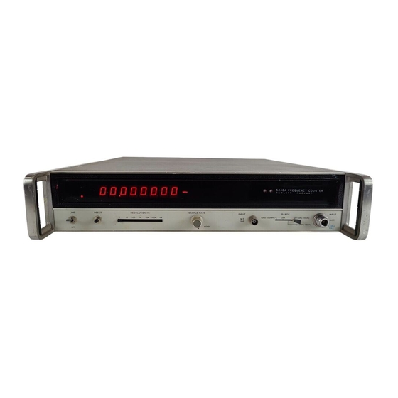
HP 5340A Calibration Procedure (17 pages)
FREQUENCY COUNTER
Brand:
HP
| Category:
Measuring Instruments
| Size: 0.1 MB
Table of Contents
Table of Contents
1
Paragraph Page
2
Identification and Description
2
Test Instrument Identification
2
Forms, Records, and Reports
3
Calibration Description
3
Equipment Requirements
4
Equipment Required
4
Accessories Required
4
Calibration Process for Frequency Counter Hewlett-Packard, Model 5340A
5
Preliminary Instructions
5
Advertisement
Related Products
HP 5372A
HP 5383A
HP 5342A/H14
HP 5342A/H16
HP 5342A
HP 5343A
HP 532A
HP 532B
HP 54750A
HP 54620C
HP Categories
Desktop
Laptop
Server
Monitor
Switch
More HP Manuals
Login
Sign In
OR
Sign in with Facebook
Sign in with Google
Upload manual
Upload from disk
Upload from URL