Table of Contents
Advertisement
DEPARTMENT OF THE ARMY TECHNICAL BULLETIN
MICROWAVE FREQUENCY COUNTER
TD-1225A(V)1/U (HEWLETT-PACKARD, MODEL 5342A/H14),
TD-1225A(V)2/U (HEWLETT-PACKARD, MODEL 5342A/H16) AND
HEWLETT-PACKARD, MODELS 5342A AND 5343A
Headquarters, Department of the Army, Washington, DC
You can help improve this publication by calling attention to errors and by
recommending
recommendations.
Publications, should be mailed directly to Commander, U. S. Army Aviation and
Missile Command, ATTN: AMSAM-TMD-LP, Redstone Arsenal, AL 35898-5000.
FAX to DSN 788-2313 (Commercial: 256-842-2313),. A reply will be furnished
directly to you.
SECTION
___________
*This bulletin supersedes TB 9-6625-2021-35, dated 20 June 1997.
*TB 9-6625-2021-35
SUPERSEDED COPY DATED 20 JUNE 1997
CALIBRATION PROCEDURE FOR
FREQUENCY COUNTER
HEWLETT-PACKARD, MODEL 5340A
Approved for public release, distribution is unlimited.
REPORTING OF ERRORS
improvements
Your letter or DA Form 2028, Recommended Changes to
Test instrument identification ..........................
Forms, records, and reports .............................
Calibration description .....................................
Equipment required .........................................
Accessories required .........................................
Preliminary instructions .........................................
AND
26 June 2000
and
stating
your
reasons
for
the
Page
1
2
3
4
5
6
2
3
3
4
4
5
Advertisement
Table of Contents

Subscribe to Our Youtube Channel
Related Manuals for HP 5340A


Summary of Contents for HP 5340A
-
Page 1: Table Of Contents
*TB 9-6625-2021-35 SUPERSEDED COPY DATED 20 JUNE 1997 DEPARTMENT OF THE ARMY TECHNICAL BULLETIN CALIBRATION PROCEDURE FOR FREQUENCY COUNTER HEWLETT-PACKARD, MODEL 5340A MICROWAVE FREQUENCY COUNTER TD-1225A(V)1/U (HEWLETT-PACKARD, MODEL 5342A/H14), TD-1225A(V)2/U (HEWLETT-PACKARD, MODEL 5342A/H16) AND HEWLETT-PACKARD, MODELS 5342A AND 5343A Headquarters, Department of the Army, Washington, DC 26 June 2000 Approved for public release, distribution is unlimited. -
Page 2: Paragraph Page
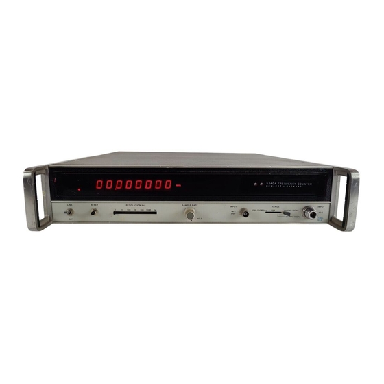
18 GHz..............Power supply ............Final procedure ............ SECTION I IDENTIFICATION AND DESCRIPTION 1. Test Instrument Identification. This bulletin provides instructions for the calibration of Frequency Counter Hewlett-Packard, Model 5340A and Microwave Frequency Counter TD-1225A(V)1/U (Hewlett-Packard, Model 5342A/H14), 1225A(V)2/U (Hewlett-Packard, Model 5342A/H16) and Hewlett-Packard, Models 5342A and 5343A. -
Page 3: Forms, Records, And Reports
3. Calibration Description. TI parameters and performance applications which pertain to this calibration are in table 1. Table 1. Calibration Description Test instrument parameters Performance specifications HEWLETT-PACKARD, MODEL 5340A Time base: Option 001 only Frequency: 10 MHz Aging rate: <±5 x 10 per day after 24 hour warm-up Line variation: <±1 x 10... -
Page 4: Equipment Requirements
TB 9-6625-2021-35 SECTION II EQUIPMENT REQUIREMENTS 4. Equipment Required. Table 2 identifies the specific equipment to be used in this calibration procedure. This equipment is issued with Secondary Transfer Calibration Standards Set AN/GSM-286. Alternate items may be used by the calibrating activity. The item selected must be verified to perform satisfactorily prior to use and must bear evidence of current calibration. -
Page 5: Calibration Process For Frequency Counter Hewlett-Packard, Model 5340A
TB 9-6625-2021-35 SECTION III CALIBRATION PROCESS FOR FREQUENCY COUNTER HEWLETT-PACKARD, MODEL 5340A 6. Preliminary Instructions a. The instructions outlined in paragraphs 6 and 7 are preparatory to the calibration process. Personnel should become familiar with the entire bulletin before beginning the calibration. - Page 6 TB 9-6625-2021-35 e. Set LINE switch to ON. If TI has been disconnected from power more than 24 hours, allow at least 24 hours for warmup and stabilization. 8. Time Base Stability - Option 001 Only a. Performance Check (1) Connect time/frequency workstation OUTPUT 1 MHz to frequency difference meter REF INPUT.
- Page 7 TB 9-6625-2021-35 (6) Adjust autotransformer output to 125 V ac. Allow 1 minute for oscillator to stabilize. Frequency difference meter indication will be within ±1 part in 10 of indication recorded in (4) above. (7) Adjust autotransformer output to 115 V ac. b.
- Page 8 TB 9-6625-2021-35 (4) Set function generator amplitude to 141 mVp-p. Adjust function generator frequency from 10 Hz to 10 MHz. If TI does not display a stable indication of applied frequency, perform b below. (5) Disconnect function generator and 50Ω feedthrough termination from TI. (6) Connect signal generator RF Output to TI INPUT 1 MΩ...
- Page 9 TB 9-6625-2021-35 (7) Set signal generator frequency to 10 MHz and level output to -30 dBm. If TI does not display a stable indication of applied frequency, perform b below. (8) Adjust signal generator frequency from 10 to 500 MHz. If TI does not display a stable indication of applied frequency, perform b below.
- Page 10 TB 9-6625-2021-35 (8) Increase signal generator level output by 1 dB from level recorded in (6) above and adjust A17A1R22 (fig. 1) ccw until TI display indicates 100 MHz (R). (9) Verify that sensitivity is at least -32 dBm. 12. Power Supply NOTE Do not perform power supply check if all other parameters are within tolerance.
- Page 11 TB 9-6625-2021-35 SECTION IV CALIBRATION PROCESS FOR MICROWAVE FREQUENCY COUNTER TD-1225A(V)1/U (HEWLETT-PACKARD, MODEL 5342A/H14), TD-1225A(V)2/U (HEWLETT-PACKARD, MODEL 5342A/H16), AND HEWLETT-PACKARD, MODELS 5342A AND 5343A 14. Preliminary Instructions a. The instructions outlined in paragraphs 14 and 15 are preparatory to the calibration process.
- Page 12 TB 9-6625-2021-35 (1) INT/EXT switch (rear panel) to INT. (2) CW/FM switch (rear panel) to CW (model 5342A only). (3) ACQ TIME/FAST, MED, SLOW switch (rear panel) to MED (model 5343A only). (4) SAMPLE RATE control fully ccw. (5) Frequency range switch 10 Hz - 500 MHz/500 MHz - 18 GHz (10 Hz - 500 MHz/500 MHz - 26.5 GHz for model 5343A) to 10 Hz - 500 MHz.
- Page 13 TB 9-6625-2021-35 (4) Allow at least 24 hours for TI time base oscillator to stabilize. Frequency difference meter indication will be within ±5 parts in 10 of indication recorded in (3) above. Record frequency difference meter indication. (5) Adjust autotransformer output to 105 V ac. Allow 1 minute for oscillator to stabilize.
- Page 14 TB 9-6625-2021-35 (4) Set function generator amplitude to 71 mVp-p. (5) Adjust function generator frequency from 10 Hz to 10 MHz. If TI does not display a stable indication of applied frequency, perform b below. (6) Disconnect function generator from TI. (7) Connect signal generator RF Output to TI front panel BNC input.
- Page 15 TB 9-6625-2021-35 19. Frequency and Sensitivity Check - 500 MHz to 18 GHz a. Performance Check CAUTION Do not exceed +25 dBm peak of input power at the N type connector (500 MHz to 18 GHz), SMA connector for model 5343A.
- Page 16 TB 9-6625-2021-35 -5.2V TEST POINT FRONT PANEL Figure 3. TD-1225A(V)1/U (Hewlett-Packard, Model 5342A/H14), TD-1225A(V)2/U (Hewlett-Packard, Model 5342A/H16) and Hewlett-Packard, Model 5343A - bottom view. b. Adjustments. Adjust A21R17 (fig. 2) for - 5.2 V dc indication on multimeter (R). 21. Final Procedure a.
- Page 17 TB 9-6625-2021-35 By Order of the Secretary of the Army: Official: ERIC K. SHINSEKI General, United States Army Chief of Staff JOEL B. HUDSON Administrative Assistant to the Secretary of the Army 0015704 DISTRIBUTION: To be distributed in accordance with IDN 342184, requirements for calibration procedure TB 9-6625-2021-35.
Need help?
Do you have a question about the 5340A and is the answer not in the manual?
Questions and answers