
Related Manuals for Nvidia UFM 4.0


Summary of Contents for Nvidia UFM 4.0
- Page 1 NVIDIA UFM 4.0 Cyber-AI Appliance Hardware User Manual Exported on Nov/26/2023 08:52 AM...
-
Page 2: Table Of Contents
Table of Contents About This Document................5 Ordering Part Numbers................5 Intended Audience ...................5 Technical Support ..................5 Related Documentation ................5 Overview ..................6 UFM Cyber-AI Appliance Highlights..............6 List of Hardware Features ................6 Main System Components................7 Network Interface Cards................ 7 Power Supply Units ................7 Fans .................... - Page 3 Safety Warnings ................15 Taiwan RoHS Declaration - Switch Systems ..........17 Taiwan RoHS Declaration - Gateway Systems..........18 Taiwan BSMI Class A Statement - Warning to the User! ........18 Installing Appliance in Rack ..............18 Slide Rail Installation................19 System Monitoring ................24 Power-on LED ..................
-
Page 5: About This Document
UFM Enterprise, UFM Telemetry, 2U server with 2 ConnectX®-6 HDR 200Gb/s InfiniBand adapters Intended Audience This manual is intended for IT managers and system administrators. Technical Support Customers who purchased NVIDIA products directly from NVIDIA are invited to contact us through the following methods: • E-mail: enterprisesupport@nvidia.com •... -
Page 6: Overview
The NVIDIA® UFM® Cyber-AI Appliance (Gen 4.0) solution enhances the benefits of UFM Telemetry and UFM Enterprise, providing scale-out of preventive maintenance for lowering supercomputing OPEX. UFM Cyber-AI Appliance... -
Page 7: Main System Components
The server must support, via BIOS, three RAID RAID configuration simultaneals • RAID 1 for 2 Disk HDD • RAID 10 for 4 Disk HDD • RAID 1 for 2 Disk SSD 2x1GbE management ports IPv4/6 & 2x10GbE3 OOB Networking DB9 RS232 port male Serial Port PCI Express 3.0 x16... -
Page 8: Fans
The operating environment should meet severity level G1 as per ISA 71.04 for gaseous contamination and ISO 14644-1 class 8 for cleanliness level. Airflow Requirements NVIDIA UFM Cyber-AI appliance is offered with one airflow pattern: From the front panel to the rear panel. Please refer to the Technical Specifications section for airflow numbers. -
Page 9: Regulatory Certifications
• Detects performance degradations • Detects usage profile changes over time • Detects abnormal cluster behavior • Correlates between seemingly unrelated phenomena powered by artificial intelligence • Alerts when preventive maintenance is needed • Continuous system data collection to optimize predictability Regulatory Certifications Country Certification... -
Page 10: System Layout And Interfaces
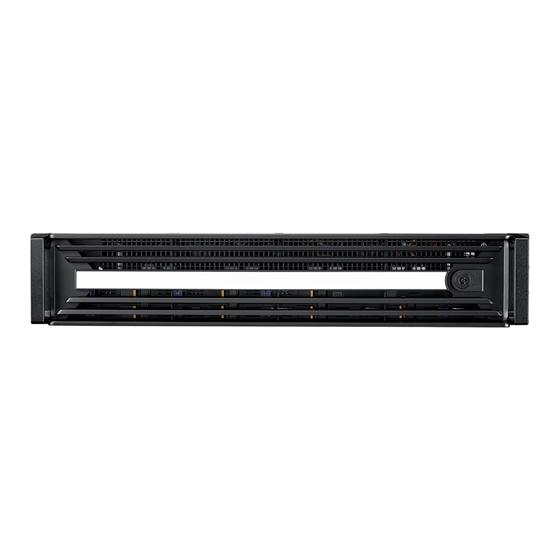
System Layout and Interfaces The following figures show the front and rear sides of NVIDIA® UFM® Cyber-AI Appliance. Each numbered interface referenced in the following figures is described in the table that follows. Appliance Front and Rear Panel Interfaces Interface... -
Page 11: Power-On Led
Power-on LED There is one I/O LED (green) on the front panel to indicate if the system is powered. For power-on LED definitions, please refer to section "Power-on LED". USB 3.0 Interfaces UFM Cyber-AI Appliance offers 4x USB 3.0 ports on the system's rear panel. These interfaces can be used to provide up to 500MB/s in bandwidth. ... -
Page 12: Fan Modules
80 PLUS Platinum 1+1 redundant power supply: • 1000W @ 100 ~127V • 2000W @ 200 ~240V For the redundant power module LEDs definitions, please refer to Power Module LED Specifications. Fan Modules Power Supply Fans UFM Cyber-AI Appliance is equipped with one fan per power supply unit on the rear panel of the appliance. ... -
Page 13: Hardware Installation
Hardware Installation Installation of the NVIDIA UFM Cyber-AI appliance requires attention to the mechanical and power elements of the appliance and precautions must be taken for the rack-mounted equipment. The system platform can be rack-mounted and is designed for installation in a standard 19” rack. -
Page 14: Rack Mounting
Harness RS232 2m cable – DB9-to-RJ45 Harness Do not connect to the COM port. Ethernet CAT6A 2m cable – RJ45-to-RJ45 Ethernet Cable Quick installation guide Documentation Rail Kit Package Contents Item type Item description Slides Set of rack slides Screw M5* 15L M5* 15L –... -
Page 15: Safety Warnings
Safety Warnings Prior to the installation, make sure to review the safety warnings. Note that not all warnings may apply to the UFM Cyber-AI Appliance. Safety warnings are provided here in the English language. For safety warnings in other languages, refer to the 1U Switch Installation Safety Instructions document. - Page 16 Multiple Power Inlets Risk of electric shock and energy hazard. The PSUs are all independent. Disconnect all power supplies to ensure a powered down state inside of the switch platform. During Lightning—Electrical Hazard During periods of lightning activity, do not work on the equipment or connect or disconnect cables.
-
Page 17: Taiwan Rohs Declaration - Switch Systems
Overcurrent Protection A readily accessible Listed branch circuit overcurrent protective device rated 20 A must be incorporated in the building wiring. Acoustic Level Warning The acoustic level listed in Specifications section represents product noise measured in accordance with ISO 7779 under nominal conditions. The actual noise level can vary depending on the installation conditions, including but not limited to the number of racks in the installation, the overall installation size, rack and other equipment material and noise levels, fan faults, room temperature, room configuration, and employee... -
Page 18: Taiwan Rohs Declaration - Gateway Systems
Taiwan RoHS Declaration - Gateway Systems Taiwan BSMI Class A Statement - Warning to the User! 警告:為避免電磁干擾,本產品不應安裝或使用於住宅環境。 Installing Appliance in Rack Before mounting UFM Cyber-AI Appliance in a rack, ensure that all internal components are installed, and that the unit has been fully tested. Both sides of the chassis ear must be assembled with screws (PN:1930005209) after you assemble the slide rail kit. -
Page 19: Slide Rail Installation
Slide Rail Installation The UFM Cyber-AI Appliance slides are developed for 1U or 2U applications whose system load does not exceed 34 kgs. The slide length is 1041±3.0 mm. The rear bracket is extendable to a max/min post-to-post distance of 670-1042 mm. The slide extension is 610.0±3.0 mm. - Page 20 Remove the inner member. Pull inner member out as shown in the following figure. Mount the inner member onto the chassis. Place the key slot on T stud and push the inner member toward the back. Mount the cabinet member to the posts. Align the positioning pin to the desired complete U location, and pull the bracket forwards to lock it to the post.
- Page 21 post after you hear a “click” sound. Release the locking latch upward.
- Page 22 Push the middle member forward to the rear of the slide. Install the chassis. As shown, insert the inner member to the cabinet member. Make sure the ball retainer is in the open position. It might cause damage to the slides if the ball retainer is not on the front position.
- Page 23 7. Screw the system in the cabinet. Rack Mount Instructions The following or similar rack-mount instructions are included with the installation procedure: • Elevated Operating Ambient – if installed in a closed or multi-unit rack assembly, the operating ambient temperature of the rack environment may be greater than the room ambient.
-
Page 24: System Monitoring
System Monitoring This section lists the monitoring LEDs available on the NVIDIA® UFM® Cyber-AI Appliance. Power-on LED There is one I/O LED (green) on the front panel to indicate if the system is powered. LED state Color Description Green System is turned on... -
Page 25: Power Module Led
LAN3/LAN4 Rear I/O LED Interface Left LED Right LED Description Green Active – 10Mbps Blinking green Active – 10Mbps Amber Green Active – 100Mbps Amber Blinking green Active – 100Mbps Green Green Linked – 1Gbps Green Blinking green Active – 1Gbps No link Power Module LED There are two I/O LEDs (Green and Amber) to indicate the power module state. - Page 26 LED Color and State Description Blinking amber 1Hz blinking amber occurs due to running a beacon command to locate the adapter card 4Hz blinking amber indicates a problem with the physical link Solid green Indicates a valid link with no active traffic Blinking green Indicates a valid logical link with active traffic InfiniBand Network Port LED Behavior LED Color and State...
-
Page 27: Technical Specifications
Technical Specifications UFM Cyber-AI Appliance Specifications Dimensions (W x H x D): 438 x 88 x 760 (17.24" x 3.46" x 29.92") Physical Weight: 35kg Mounting: 19” Rack mount InfiniBand: IBTA v1.3a Supported Auto-Negotiation: 1X/2X/4X SDR (2.5Gb/s per lane), DDR (5Gb/s per lane), QDR (10Gb/s per Protocols lane), EDR (25Gb/s per lane) port, HDR100 (2 lane x 50Gb/s per lane), HDR (50Gb/s per lane) port... -
Page 28: System Dimensions
Vibration (5 0.25 GRMs ~ 500 Hz) Shock 10G (with 11ms duration, half sine wave) Airflow/heat dissipation: Thermal • 1045 LFM when all 6 fans are working at full speed • 688 LFM when only 4 fans are working at full speed System Dimensions ... -
Page 29: Inventory Information
Inventory Information The system’s inventory parameters (i.e. serial number, part number) can be extracted from labels on the system's bottom side. -
Page 30: Field Replaceable Units
Description MUA96-PF Power supply w/ PSU-side to connector-side airflow for NVIDIA® UFM® 4.0 2U server MUA96-SKIT Rack installation kit for NVIDIA® UFM® 4.0 2U server standard depth racks MUA96-HD NVIDIA® UFM® 4.0 – hard drive FRU MUA96-SD NVIDIA® UFM® 4.0 – solid-state drive FRU MUA96-GPU NVIDIA®... -
Page 31: System Configuration
System Configuration IP Address Configuration The system comes with a default system root user: root/UFMcyberAI Whether the user wants to configure static or dynamic IP addresses, they may use standard Linux tools to configure it while logged in as root user. ... -
Page 32: Document Revision History
Document Revision History Date Description of Changes Rev 1.0 Mar 31, 2022 First release... - Page 33 NVIDIA accepts no liability related to any default, damage, costs, or problem which may be based on or attributable to: (i) the use of the NVIDIA product in any manner that is contrary to this document or (ii) customer product designs.
- Page 34 Copyright © 2023 NVIDIA Corporation & affiliates. All Rights Reserved.
Need help?
Do you have a question about the UFM 4.0 and is the answer not in the manual?
Questions and answers