Table of Contents
Advertisement
Quick Links
AVerMedia D133 series【Preliminary】
®
Applies to NVIDIA
Jetson Orin™ NX/ Orin™ NANO Module
AVerMedia Technologies, Inc.
No. 135, Jian 1st Rd., Zhonghe Dist., New Taipei City 23585, Taiwan
Tel: 886-2-2226-3630
Fax: 886-2-3234-4842
Sales and Marketing:
Contact
Technical Support:
Professional User
0
D131 User Manual AVerMedia Technologies, Inc www.avermedia.com
Advertisement
Table of Contents

Related Manuals for Nvidia AVerMedia D133 Series


Summary of Contents for Nvidia AVerMedia D133 Series
- Page 1 AVerMedia D133 series【Preliminary】 ® Applies to NVIDIA Jetson Orin™ NX/ Orin™ NANO Module AVerMedia Technologies, Inc. No. 135, Jian 1st Rd., Zhonghe Dist., New Taipei City 23585, Taiwan Tel: 886-2-2226-3630 Fax: 886-2-3234-4842 Sales and Marketing: Contact Technical Support: Professional User...
-
Page 2: Table Of Contents
Table of Contents Preface ......................2 1.0 Introduction ....................8 1.1 Product Specifications ..................9 1.2 Option Accessory ..................12 2.0 Product Overview ................... 13 2.1 Block Diagram ....................13 2.2 Front View and Back View of Carrier board ..........14 2.3 Connector Summary .................. -
Page 3: Preface
Preface Disclaimer The information contained in this user manual, including but not limited to any product specification is subject to change without notice. AVerMedia assumes no liability for any damages incurred directly or indirectly from any technical or typographical errors or omissions contained herein or for discrepancies between the product and the user manual. - Page 4 Revision History Revision Date Updates Version 1.0 Oct, 11, 2023 Released D131 User Manual AVerMedia Technologies, Inc www.avermedia.com...
- Page 5 AVerMedia Global Offices https://www.avermedia.com/professional/contact-us D131 User Manual AVerMedia Technologies, Inc www.avermedia.com...
- Page 6 Limited Product Warranty AVerMedia provides three-year product warranty. Should this product, in AVerMedia's opinion, fail to be in the good working order during the warranty period, AVerMedia will, at its option, repair or replace it at no charge, provided that the product has not been subjected to abuse, misuse, accident, disaster, or non-AVerMedia authorized modification or repair.
- Page 7 Trademark Acknowledgement AVerMedia acknowledges all the trademarks, registered trademarks, and/or copyrights referred to in this document as the property of their respective owners. Not listing all possible trademarks or copyright acknowledgments does not constitute the lack of acknowledgment to the rightful owners of the trademarks and copyrights mentioned in this document. ESD Warning Electronic components and circuits are sensitive to Electrostatic Discharge (ESD).
- Page 8 10. Disconnect the device from any AC supply before cleaning. While cleaning, use a damp cloth instead of liquid or spray detergents. 11. Make sure the device is installed near a power outlet and easy for accessible. 12. Do not cover the openings on the device to ensure optimal heat dissipation. 13.
-
Page 9: Introduction
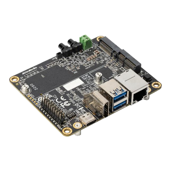
1.0 Introduction AVerMedia D133/D133ON/D133ONB is a fully featured carrier board/engineering kit/box PC designed for NVIDIA® Jetson Orin Nano modules. AVerMedia provides access to a wide range of latest interfaces on NVIDIA® Jetson Orin Nano modules. D133/D133ON/D133ONB provide HDMI video output , two USB 3.2 ports, one GbE RJ-45 port, 20-pin expansion header, and one USB 2.0 type C port for recovery. -
Page 10: Product Specifications
Model D133 Type Carrier board NVIDIA GPU SoC NVIDIA® Jetson Orin NANO-8G/4G module Module NVIDIA® Jetson Orin NX -16G/8G module (TBD) Compatibility 1x GbE RJ-45 Networking 1xM.2. key E 2230 for Wi-Fi 1x HDMI 4Kp30 for Orin Nano Display Output 1x HDMI 4Kp60 for Orin NX (TBD) Operating temperature -25°C~85°C... - Page 11 D133ON Type Engineering kit NVIDIA GPU SoC NVIDIA® Jetson Orin NANO-8G/4G module Module NVIDIA® Jetson Orin NX -16G/8G module (TBD) Compatibility 1 x GbE RJ-45 Networking 1 x M.2. key E 2230 for wifi 1x HDMI 4Kp30 for Orin Nano...
- Page 12 D133ONB Type Box PC NVIDIA GPU SoC NVIDIA® Jetson Orin NANO-8G/4G module Module NVIDIA® Jetson Orin NX -16G/8G module (TBD) Compatibility 1 x GbE RJ-45 Networking 1 x M.2. key E 2230 for wifi 1x HDMI 4Kp30 for Orin Nano...
-
Page 13: Option Accessory
1.2 Option Accessory Item D133/D133ON/ D133ONB Jetson Orin™ Nano for D133ON/D133ONB ® NVIDIA NVIDIA® Jetson Jetson Orin™ NX for D133OX/D133OXB (TBD) ® NVIDIA Power adapter/ 12V/5A adapter and US/JP/EU/UK/TW/AU/CN power cord Power Cord (optional) ⚫ For 22 pin MIPI connector... -
Page 14: Product Overview
2.0 Product Overview 2.1 Block Diagram D131 User Manual AVerMedia Technologies, Inc www.avermedia.com... -
Page 15: Front View And Back View Of Carrier Board
2.2 Front View and Back View of Carrier board D131 User Manual AVerMedia Technologies, Inc www.avermedia.com... - Page 16 2.3 Front View and Three -Quarter View of BoxPC Left view Right view D131 User Manual AVerMedia Technologies, Inc www.avermedia.com...
- Page 17 Top view Front View D131 User Manual AVerMedia Technologies, Inc www.avermedia.com...
- Page 18 Back view D131 User Manual AVerMedia Technologies, Inc www.avermedia.com...
-
Page 19: Connector Summary
2.3 Connector Summary Front View Interface External RTC Battery wafer DC power jack Gigabit Ethernet Connector w/LEDs USB 3.0 Gen1 Dual Port Type A Connector HDMI Type-A Vertical Side Connector with lock (Female) M.2 E-Key Socket USB type C 20-pin Expansion M.2 M-Key Socket DIP switch Power Button w/LEDs... - Page 20 Back View Interface SO-DIMM 260-pin 90° SMD Socket(H-9.2mm) for Jetson Orin™ NX/ Orin™ Nano SOM Fan Wafer FPC connector for 4-lane MIPI CSI-2 FPC connector for 4-lane MIPI CSI-2 D131 User Manual AVerMedia Technologies, Inc www.avermedia.com...
-
Page 21: Feature Description
DIMM_260PIN_90° Manufacturer and Foxconn ASAA826-EASB0-7H Part Number Orin™ N NVIDIA® Jetson X/Orin Mating Connector Nano Please refer to NVIDIA Jetson System- Pinout on-Module datasheet for pinout details. Remarks https://developer.nvidia.com/embedded/downloads 3.2 RTC Battery Connector Function RTC battery for module Location Type Description WAFER_1*2PIN_1.25 ㎜_90°_SMD... -
Page 22: Dc Power Jack
3.3 Power Supply Connector Function Power Supply Location Type Description Socket_Terminal Block_1*2PIN_90° Manufacturer and DECA MB332-350M02 Part Number Mating Connector DC 5.5 x 2.5 mm Power cable PIN# Description Color Pinout 12-24V White Black Remarks None 3.4 Gigabit Ethernet Connector 1Gb single-port Ethernet connector, used Function to connect to the host system. -
Page 23: Hdmi Output
and Part Number Mating Any USB 3.2 standard Type-A interface cable or device. Connector Please refer to USB 3.2 standard. Pinout None Remarks 3.6 HDMI OUTPUT Function HDMI output connector Location Type Description HDMI Type-A female connector Manufacturer and 捷湧 EDL HM-FVD480B Part Number Any HDMI standard Type-A... -
Page 24: Usb Type C Connector
3.8 USB type C Connector Function BSP Installation as recovery mode Location Type Description JACK_USB_C TYPE(F)_90°_PIP-L1.45 ㎜ Manufacturer and 宏致 ACES, 57988-0240D-001 Part Number Mating Connector Any USB type C standard interface cable PIN OUT Please refer to USB type C standard. 3.9 M.2 M key 2280 Function M.2 M key... -
Page 25: Power Button
3.11 Power Button Function Power button Location Type Description Button Manufacturer and 冠泰Champway, LS67AK-NBR-A- Part Number R2KA9 Pinout None Remark 3.12 Recovery Button Function Recover button Location Type Description Button Manufacturer and 冠泰Champway, LS67AK-NBR-A- Part Number R2KA9 Pinout None Remark 3.13 20-Pin GPIO expansion Function General-purpose input/output... -
Page 26: Mipi Csi-2 Dphy Lanes
Pinout 3.14 MIPI CSI-2 DPHY Lanes Function MIPI camera module connector Location J14 , J16 Type WAFER_22PIN_0.5 ㎜_180° Description Manufacturer 50554-02241-003 宏致_ACES, and Part 0.5mm ZIF FPC CONN. SMT S/T TYPE Number Mating 4 Lane MIPI CSI-2 camera connector (22Pin) Connector Description 22-pin Index... - Page 27 Pin7 Pin8 CSI1_D1_P CSI1_D1_N Pin9 Pin10 CSI1_D0_P Pin11 Pin12 CSI1_D0_N Pin13 Pin14 CSI0_CLK_P CSI0_CLK_N Pin15 Pin16 CSI0_D1_P Pin17 Pin18 CSI0_D1_N Pin19 Pin20 CSI0_D0_P CSI0_D0_N Pin21 Pin22 Description 22-pin Index Description +3V3_MIPI Pin1 Pin2 CAM1_I2C_SDA CAM1_I2C_SCL Pin3 Pin4 CAM1_MCLK Pin5 Pin6 CAM1_PWDN_LS Pin7 Pin8...
-
Page 28: Fan Power Connector
3.15 Fan Power connector Function Fan Power Connector Location Type Description WAFER_1*4PIN_1.25 ㎜_90° Manufacturer ACES 50271-0040N-001_BLACK and Part Number Mating ACES 50276-004H0H0-001 Connector Pin # Description PIN 1 Pinout PIN 2 +5V Power PIN 3 FAN_TACH PIN 4 FAN_PWM Remarks None 3.16 Other Switches and Jumpers Other switches and jumpers listed on the boards but not mentioned in this manual are... -
Page 29: Installation
You have to keep pressing “Recovery” button and then power on the NVIDIA Jetson board to initiate recovery mode. When connecting a NVIDIA Jetson board to a Linux PC via a MicroUSB to USB cable, you can check kernel messages with `dmesg` command in the Linux PC. -
Page 30: Software
# get current power mode $ sudo nvpmodel -q # setup power mode # where <x> is power mode number, please refer to https://docs.nvidia.com/jetson/archives/r35.2.1/DeveloperGuide/index.html#page/T egra%20Linux%20Driver%20Package%20Development%20Guide/clock_power_s etup.html# for more information $ sudo nvpmodel -m <x> * Current default power mode:... - Page 31 Fan Speed The following commands can get PWM fan information. # get Fan RPM value $ cat /sys/devices/platform/gpio_tachometer/hwmon/hwomn1/gpiotach_rpm MIPI CSI Camera There are 2x 2-lane and 1x 4-lane MIPI CSI camera supported on D133ONB, for current supported products type are listing as below: * IMX219 (2-lane) * IMX477 (2-lane): IMX477 requires a hardware modification in order to work with Jetson Platforms.
- Page 32 raw(memory:NVMM), width=(int)1280, height=(int)720, format=(string)NV12, framerate=(fraction)60/1' ! queue ! nvvidconv ! xvimagesink -e Multiple: $ gst-launch-1.0 nvarguscamerasrc sensor-id=0 ! 'video/x- raw(memory:NVMM), width=(int)3264, height=(int)2464, format=(string)NV12, framerate=(fraction)21/1' ! queue ! nvvidconv ! xvimagesink -e & gst-launch-1.0 nvarguscamerasrc sensor-id=1 sensor-mode=0 ! 'video/x-raw(memory:NVMM), width=(int)3264, height=(int)2464, format=(string)NV12, framerate=(fraction)21/1' ! nvvidconv ! xvimagesink -e &...
- Page 33 raw(memory:NVMM), width=(int)1920, height=(int)1080, format=(string)NV12, framerate=(fraction)30/1' ! queue ! nvvidconv ! xvimagesink -e $ gst-launch-1.0 nvarguscamerasrc sensor-id=0 ! 'video/x- raw(memory:NVMM), width=(int)3280, height=(int)1698, format=(string)NV12, framerate=(fraction)30/1' ! queue ! nvvidconv ! xvimagesink -e $ gst-launch-1.0 nvarguscamerasrc sensor-id=0 ! 'video/x- raw(memory:NVMM), width=(int)2096, height=(int)1084, format=(string)NV12, framerate=(fraction)30/1' ! queue ! nvvidconv ! xvimagesink -e $ gst-launch-1.0 nvarguscamerasrc sensor-id=0 ! 'video/x- raw(memory:NVMM), width=(int)1640, height=(int)1232, format=(string)NV12,...
- Page 34 2 640 25/30/50/60 $ gst-launch-1.0 v4l2src io-mode=4 device=/dev/video0 do-timestamp=true ! 'video/x-raw, width=1920, height=1080, framerate=60/1, format=UYVY' ! queue ! xvimagesink sync=false $ gst-launch-1.0 v4l2src io-mode=4 device=/dev/video0 do-timestamp=true ! 'video/x-raw, width=1280, height=960, framerate=30/1, format=UYVY' ! queue ! xvimagesink sync=false $ gst-launch-1.0 v4l2src io-mode=4 device=/dev/video0 do-timestamp=true ! 'video/x-raw, width=1280, height=720, framerate=30/1, format=UYVY' ! queue ! xvimagesink sync=false $ gst-launch-1.0 v4l2src io-mode=4 device=/dev/video0 do-timestamp=true !
- Page 35 $ gst-launch-1.0 nvarguscamerasrc sensor-id=0 ! 'video/x- raw(memory:NVMM), width=(int)1944, height=(int)1090, format=(string)NV12, framerate=(fraction)60/1' ! queue ! nvvidconv top=5 bottom=1085 left=12 right=1932 ! xvimagesink –e GPIO usage ➢ For JetPack5.x (1) Output: (e.g. gpio 398) $ sudo su $ gpio_id=398 $ sudo cat /sys/kernel/debug/gpio | grep ${gpio_id} # output: gpio-398 (PH.07 $ gpio_index=PH.07...
- Page 36 Press and hold down Force Recovery Button and then power on the carrier board. After three seconds, release Force Recovery Button. NVIDIA® Orin NX will show up on the USB list of the host system as a new NVIDIA target device.
-
Page 37: Dimension Drawings
6.0 Dimension Drawings 6.1Dimension Drawings of carrier board D131 User Manual AVerMedia Technologies, Inc www.avermedia.com... -
Page 38: Dimension Drawing Of Pse Board
6.2 Dimension Drawing of Box PC D131 User Manual AVerMedia Technologies, Inc www.avermedia.com... -
Page 39: Accessory Drawings
7.0 Accessory Drawings 7.1 Fan Module/ Adapter/ Power Cord Fan Module for Orin Nano ◼ Rated Voltage: 5V ◼ Operating Voltage Range: 3.5V~5.5V ◼ Rated Speed: 7000RPM±10% (Testing Speed After Continuous 3 Minute Operation At Ambient Temperature Of 25℃) ◼ Life Expectancy: 70,000hours at 40℃ (WITH 15~65% RH) ◼... - Page 40 D131 User Manual AVerMedia Technologies, Inc www.avermedia.com...
- Page 41 Power Adapter 04131HGOUANK 064APOWERBRX-IPD (TW version) D131 User Manual AVerMedia Technologies, Inc www.avermedia.com...
- Page 42 064APOWERBR2-IPD (US version) 064APOWERBRW-IPD (UK version) D131 User Manual AVerMedia Technologies, Inc www.avermedia.com...
- Page 43 064APOWERBR5-IPD (EU version) D131 User Manual AVerMedia Technologies, Inc www.avermedia.com...
- Page 44 064APOWERBSL (JP version) 064APOWERBR4-IPD (CN version) D131 User Manual AVerMedia Technologies, Inc www.avermedia.com...
Need help?
Do you have a question about the AVerMedia D133 Series and is the answer not in the manual?
Questions and answers