Table of Contents
Advertisement
Quick Links
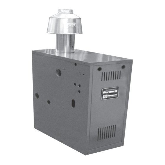
Installation, Operating and Service Instructions for
SERIES 2
Models:
• 202E
• 203E
• 204E
• 205E
• 206E
• 207E
• 208E
• 209E
Manual Contents
Specifications . . . . . . . . . . . . . . . . . . . . . . . . . . 3
Pre-installation . . . . . . . . . . . . . . . . . . . . . . . . . . 4
Removing Existing Boiler . . . . . . . . . . . . . . . . . 5
Clearances . . . . . . . . . . . . . . . . . . . . . . . . . . . . . 5
Venting . . . . . . . . . . . . . . . . . . . . . . . . . . . . . . . . 7
Water Piping . . . . . . . . . . . . . . . . . . . . . . . . . . . 10
Gas Piping . . . . . . . . . . . . . . . . . . . . . . . . . . . . 13
Electrical . . . . . . . . . . . . . . . . . . . . . . . . . . . . . . 14
System Start-Up and Checkout . . . . . . . . . . . 17
Operation . . . . . . . . . . . . . . . . . . . . . . . . . . . . . 21
Before Leaving Jobsite . . . . . . . . . . . . . . . . . . 25
Service and Maintenance . . . . . . . . . . . . . . . . 26
How It Works . . . . . . . . . . . . . . . . . . . . . . . . . . 30
Troubleshooting . . . . . . . . . . . . . . . . . . . . . . . . 32
Service Parts . . . . . . . . . . . . . . . . . . . . . . . . . . 37
Appendix . . . . . . . . . . . . . . . . . . . . . . . . . . . . . 44
TO THE INSTALLER:
Affix these instructions adjacent to boiler.
Provide model number and serial number when
seeking information and support.
TO THE CONSUMER:
Retain these instructions for future reference.
Contact heating contractor for all issues and support.
Improper installation, adjustment, alteration, service or maintenance can cause property damage, injury, or
loss of life. For assistance or additional information, consult a qualified installer, service agency or the gas
supplier. Read these instructions carefully before installing.
109443-02 - 12/19
®
Page
!
WARNING
• Water Boiler
• Cast Iron
• Chimney Vent
• Gas Fired
9700609
Advertisement
Table of Contents

Subscribe to Our Youtube Channel
Related Manuals for U.S. Boiler Company 202E


Summary of Contents for U.S. Boiler Company 202E
-
Page 1: Table Of Contents
Installation, Operating and Service Instructions for SERIES 2 ® • Water Boiler • Cast Iron • Chimney Vent • Gas Fired Models: • 202E • 203E • 204E • 205E • 206E • 207E • 208E • 209E Manual Contents Page Specifications . - Page 2 Installation, Operating & Service Manual SERIES 2E The City of New York requires a Licensed Master Plumber supervise the installation of this product. The Massachusetts Board of Plumbers and Gas Fitters has listed the Series 2E Boiler. See the Massachusetts Board ®...
-
Page 3: Specifications
SERIES 2E Installation, Operating & Service Manual Specifications Table 1A: Ratings Boiler Model Number Input (MBH) DOE Heating Capacity (MBH) AHRI Net Rating (MBH) AFUE 202E 84.0 203E 84.0 204E 84.0 205E 84.0 206E 84.0 207E 84.0 208E 84.0 209E 84.0... -
Page 4: Pre-Installation
H. Protect gas ignition system components from water (dripping, spraying, rain, etc.) during boiler operation and service (circulator replacement, condensate trap, control replacement, etc.). Conversion Kits 202E 203E 204E 205E 206E 207E... -
Page 5: Removing Existing Boiler
2. Closet Installation - B. Provide Combustion and Ventilation Air in Models 202E, 203E, 204E, 205E & 206E are accordance with the section "Air for Combustion listed for closet installation. See Figure 4-1. and Ventilation", of the National Fuel Gas Code, ANSI Z223.1/NFPA, or applicable provisions of... - Page 6 Installation, Operating & Service Manual SERIES 2E Clearances (continued) Model 202E 6" 14" 203E 6" 14" 204E 6" 16" 205E 6" 19" 206E 6" 22" Note: "A" dimension may be reduced to 4" on above models if back wall is made of a noncombustible material.
-
Page 7: Venting
SERIES 2E Installation, Operating & Service Manual Venting A. Inspect chimney and remove any obstructions D. Install Blocked Vent Switch or restric tions. Clean chimney if previously used The blocked vent switch assembly shipped taped for solid or liquid fuel-burning appliances or to the top of boiler includes a harness and a fireplaces. - Page 8 Installation, Operating & Service Manual SERIES 2E Venting (continued) E. Install Vent Damper 5. For 2 section boiler only, install supplied vent OPEN THE VENT DAMPER CARTON and remove reducer after damper. See Figure 5-1. Installation Instructions. READ INSTALLATION Install Vent Piping INSTRUCTIONS THOROUGHLY before proceeding.
- Page 9 SERIES 2E Installation, Operating & Service Manual Venting (continued) G. Install vent termination (Masonry chimney and 2. For terminations located at least 8 ft. from single wall metal pipe) vertical wall or similar obstruction, termination shall extend above roof in accordance with 1.
-
Page 10: Water Piping
Installation, Operating & Service Manual SERIES 2E Water Piping C. Install safety relief valve. See Figure 6-1. Safety WARNING relief valve must be installed with spindle in Failure to properly pipe boiler may result in vertical position. improper operation and damage to boiler or building. - Page 11 SERIES 2E Installation, Operating & Service Manual Water Piping (continued) 109443-02 - 12/19...
- Page 12 Installation, Operating & Service Manual SERIES 2E Water Piping (continued) 109443-02 - 12/19...
-
Page 13: Gas Piping
SERIES 2E Installation, Operating & Service Manual Gas Piping A. Size gas piping. Design system to provide adequate gas supply to boiler. Consider these factors: 1. Allowable pressure drop from point of delivery to boiler. Maximum allowable system pressure is ½ psig. Minimum gas valve inlet pressure is listed on rating label. -
Page 14: Electrical
Installation, Operating & Service Manual SERIES 2E Electrical C. Wire boiler. Boiler is rated for 120 VAC, 60 HZ, WARNING less than 12 A. A separate electrical circuit must be run from the main electrical service with an Electrical Shock Hazard. Wiring errors can over-current device/disconnect in the circuit. - Page 15 SERIES 2E Installation, Operating & Service Manual Electrical (continued) Figure 8-1: Wiring Connection Diagram 109443-02 - 12/19...
- Page 16 Installation, Operating & Service Manual SERIES 2E Electrical (continued) Figure 8-2: Schematic Ladder Diagram 109443-02 - 12/19...
-
Page 17: System Start-Up And Checkout
SERIES 2E Installation, Operating & Service Manual System Start-Up and Checkout A. Visual Main Burner Check D. Purge Air from System Inspect burners for dislodgement during 1. Fill entire heating system with water and shipment. Rear of burners should be in vertical vent air from boiler, radiators and system, slots in rear of burner tray and front of burners one zone at a time. - Page 18 Installation, Operating & Service Manual SERIES 2E System Start-Up and Checkout (continued) Figure 9-2: Operating Instructions 109443-02 - 12/19...
- Page 19 SERIES 2E Installation, Operating & Service Manual System Start-Up and Checkout (continued) E. Perform gas leak test upstream of boiler shutoff 3. Locate and address leaks using listed valve. combustible gas detector,a non corrosive leak detection fluid or other listed leak 1.
- Page 20 Installation, Operating & Service Manual SERIES 2E System Start-Up and Checkout (continued) J. Check Main Burner Flame (see Figure 9-6) valve can prevent pressure surge that blows out manometer fluid. 1. NORMAL FLAME: 2. Adjust regulator on gas valve so manifold a.
-
Page 21: Operation
SERIES 2E Installation, Operating & Service Manual Operation Table 10-1: Sequence of Operation A. Boiler Sequence of Operation (See Table 10-1) 1. When thermostat calls for heat, control starts Status Codes displayed in STA Mode system circulator. Status Description Standby 2. - Page 22 Installation, Operating & Service Manual SERIES 2E Operation (continued) Viewing the Operating Mode Options Table: 10-4 In operating mode user may view (but Adjustable Parameters not change) boiler operating status, settings and Default Range Description troubleshooting information. 180oF 140-220°F Adjust High Limit Setting For example, when “I”...
- Page 23 SERIES 2E Installation, Operating & Service Manual Operation (continued) Table 10-5: Circulator Pre-purge Time example, More Information About Adjustable Parameters (PP_ = 2 minutes) 1. High Limit (HL_) Call for Burner turns "off" when boiler water Boiler Heat Terminal Burner Status temperature (bt) is above this value.
- Page 24 Installation, Operating & Service Manual SERIES 2E Operation (continued) 7. Domestic Hot Water (DHW) Terminal Function (dh_) b. Second heating zone (dh_ is set to second heating zone (tt2)) DHW Circulator output can be connected to a domestic hot water circulator or a second Helpful when home uses only two heating heating zone circulator.
-
Page 25: Before Leaving Jobsite
SERIES 2E Installation, Operating & Service Manual Before Leaving Jobsite Before Leaving Jobsite: Boiler and system filled with water Performed gas leak test Checked pilot burner flame Checked main burner flames Checked gas input rate Checked gas inlet pressure ... -
Page 26: Service And Maintenance
Installation, Operating & Service Manual SERIES 2E Service and Maintenance Important Product Safety Information: Refractory Ceramic Fiber Product WARNING Some boiler components use materials that contain refractory ceramic fibers (RCF). RCF has been classified as a possible human carcinogen. When exposed to elevated temperatures, RCF may change into crystalline silica, a known carcinogen. - Page 27 SERIES 2E Installation, Operating & Service Manual Service and Maintenance (continued) WARNING Service on this boiler should be undertaken only by trained and skilled personnel from a qualified service agency. Inspections should be performed at intervals specified in this manual. Maintain manual in a legible condition.
- Page 28 Installation, Operating & Service Manual SERIES 2E Service and Maintenance (continued) D. Clean Main Burners and Firebox. Inspect Temperature/Pressure Gauge 1. To remove burners for cleaning, changing 1. Water temperature needle should move with orifices, or repairs: variation in water temperature. a.
- Page 29 SERIES 2E Installation, Operating & Service Manual Service and Maintenance (continued) Q. Test Vent Damper Operation Vent damper must be in open position when main burners are operating. R. Test Functionality of LWCO See "Start-up and Checkout - Check LWCO Functionality.
-
Page 30: How It Works
Installation, Operating & Service Manual SERIES 2E How It Works Series 2E boilers are equipped with an Intelligent Hydronic Control. This control combines features such as ignition control, high limit switch, and circulator relays. Energy is saved by using a thermal purge feature that starts the circulator and delays burner start when residual heat is available in boiler. - Page 31 SERIES 2E Installation, Operating & Service Manual How It Works (continued) 109443-02 - 12/19...
-
Page 32: Troubleshooting
Installation, Operating & Service Manual SERIES 2E Troubleshooting A. Before Troubleshooting B. IDL 1200 LWCO: Amber "LOW WATER" LED indicates the boiler is not sensing water in boiler. When using troubleshooting tables, keep in mind: 1. If AMBER LED is ON and boiler is filled with 1. - Page 33 SERIES 2E Installation, Operating & Service Manual Troubleshooting (continued) C. Use Control Display ERR (ERROR) Number to Direct Troubleshooting Efforts If control detects an error it will flash “Err” (error) followed by a number. Use this number to identify boiler problem and corrective action in table below.
- Page 34 Installation, Operating & Service Manual SERIES 2E Troubleshooting (continued) D. Use STA (STATUS) Number to Guide Troubleshooting Control will flash “STA” followed by a number. Use this number to identify the boiler problem in table below: Boiler and Circulator Off Display / Status Recommended Corrective Action Boiler has not detected a call for heat (tt = off and dh = off).
- Page 35 SERIES 2E Installation, Operating & Service Manual Troubleshooting (continued) 5 . Circulator is On But Damper is Not Open Display / Status Recommended Corrective Action Control is waiting for damper to open. Damper end switch has failed to close (end switch contact is stuck open).
- Page 36 Installation, Operating & Service Manual SERIES 2E Troubleshooting (continued) 6 . Circulator is On, Damper is Open But Boiler Fails to Start (continued) Recommended Corrective Action Display / Status 1 . No Spark a. Can you hear sparking while STA 6 is displayed? - If there is no spark noise replace control.
-
Page 37: Service Parts
All Series 2E Service Parts may be obtained through your local U.S. Boiler Company Wholesale distributor. Should you require assistance in locating a U.S. Boiler Company Distributor in your area, or have questions regarding the availability of U.S. Boiler Company products or service parts, please contact U.S. Boiler Company Customer Service at (717) 481-8400 or Fax (717) 481-8408. - Page 38 Installation, Operating & Service Manual SERIES 2E Service Parts (continued) Part Number [Quantity] Description 202E 203E 204E 205E 206E 207E 208E 209E Base Wrapper Base Tray Burner Tray Base Side Insulation Base Rear Insulation Base Front Insulation 109613-02 109613-03 109613-04...
- Page 39 SERIES 2E Installation, Operating & Service Manual Service Parts (continued) Part Number [Quantity] Description 202E 203E 204E 205E 206E 207E 208E 209E Gas Valve (Natural Gas), Honeywell 109620-01 [1] VR8204C3007 Gas Valve (Natural Gas), Honeywell 109622-01 [1] VR8304P4496 Gas Valve (LP Gas), Honeywell...
- Page 40 Installation, Operating & Service Manual SERIES 2E Service Parts (continued) Part Number [Quantity] Key No. Description 202E 203E 204E 205E 206E 207E 208E 209E Control 103966-02 [1] Transformer 106034-01 [1] LWCO/ High Limit 106495-02 [1] 109443-02 - 12/19...
- Page 41 SERIES 2E Installation, Operating & Service Manual Service Parts (continued) Part Number [Quantity] Description 202E 203E 204E 205E 206E 207E 208E 209E Wrap-around Jacket Panel Not available Jacket Vestibule Panel Top Jacket Panel 109612-04 109612-05 109612-06 109612-07 109612-08 109612-09 109612-03 [1]...
- Page 42 Installation, Operating & Service Manual SERIES 2E Service Parts (continued) Part Number [Quantity] Description 202E 203E 204E 205E 206E 207E 208E 209E Water Manifold 109614-01 [1] Temperature/Pressure Gauge 105894-01 [1] 30 PSI Safety Relief Valve 109038-01 [1] Drain Valve Obtain Locally (3/4" NPT boiler connection)
- Page 43 SERIES 2E Installation, Operating & Service Manual Service Parts (continued) Part Number [Quantity] Key No. Description 202E 203E 204E 205E 206E 207E 208E 209E Power Supply Harness 109639-01 [1] Main Control Harness 109640-01 [1] Accessories: Part Number [Quantity] Key No.
-
Page 44: Appendix
Installation, Operating & Service Manual SERIES 2E Appendix: Combination Refrigeration/ Heating System A. If boiler is used in connection with refrigeration B. If boiler is connected to heating coils located in systems, boiler must be installed with chilled air handling units where they may be exposed to medium piped in parallel with the heating boiler refrigerated air, boiler piping must be equipped using appropriate valves to prevent chilled... - Page 45 Installation, Operating & Service Manual Appendix: High Altitude Installations (above 2,000 ft .) Installations above 2,000 ft. require conversion kit listed in Table A-2 A-2 High Altitude Conversion Kits Natural Gas Elevation 202E 203E 204E 205E 206E 207E 208E 209E...
- Page 46 Installation, Operating & Service Manual SERIES 2E Appendix: Low Return Water Temperatures Thermal Shock: Cast iron boilers are very robust. 110oF and below return water temperatures will not cause thermal shock to U.S. Boiler castings. Condensation is a different matter: Cast iron boilers will tolerate intermittent periods of condensation, but are not designed for extended condensation periods.
- Page 47 SERIES 2E Installation, Operating & Service Manual Appendix: Low Return Water Temperatures (continued) Primary-Secondary Pumping: This is an improvement over simple by-pass piping to reduce condensation. Again this is a fixed system. It can not adapt to variations in temperature and flow. Best Alternative: U.S.
- Page 48 Installation, Operating & Service Manual SERIES 2E Appendix: Wiring Schematics Wiring Schematic, Zone Valves Wiring Schematic, Zone Circulators 109443-02 - 12/19...
- Page 49 SERIES 2E Installation, Operating & Service Manual 109443-02 - 12/19...
- Page 50 Installation, Operating & Service Manual SERIES 2E 109443-02 - 12/19...
- Page 51 SERIES 2E Installation, Operating & Service Manual 109443-02 - 12/19...
- Page 52 Installation, Operating & Service Manual SERIES 2E U .S . Boiler Company, Inc . P .O . Box 3020 Lancaster, PA 17604 1-888-432-8887 www .usboiler .net 109443-02 - 12/19...
Need help?
Do you have a question about the 202E and is the answer not in the manual?
Questions and answers