Table of Contents
Advertisement
Quick Links
Advertisement
Table of Contents

Subscribe to Our Youtube Channel
Related Manuals for GEA Bock HA22e


Summary of Contents for GEA Bock HA22e
- Page 1 GEA Bock HA22e/HA34e Assembly instructions 96417-03.2018-Gb Translation of the original instructions HA22e/125-4 HAX22e/125-4 HA22e/160-4 HAX22e/160-4 HA22e/190-4 HAX22e/190-4 HA34e/215-4 HAX34e/215-4 HA34e/255-4 HAX34e/255-4 HA34e/315-4 HAX34e/315-4 HA34e/380-4 HAX34e/380-4...
- Page 2 Observe the safety instructions contained in these instructions. These instructions must be passed onto the end customer along with the unit in which the compres- sor is installed. Manufacturer GEA Bock GmbH 72636 Frickenhausen Contact GEA Bock GmbH Benzstraße 7...
-
Page 3: Table Of Contents
Contents Page Safety 1.1 Identification of safety instructions 1.2 Qualifications required of personnel 1.3 General safety instructions 1.4 Intended use Product description 2.1 Short description 2.2 Name plate 2.3 Type key Areas of application 3.1 Refrigerants 3.2 Oil charge 3.3 Limits of application Compressor assembly 4.1 Storage and transport 4.2 Setting up 4.3 Pipe connections 4.4 Pipes... -
Page 4: Safety
1| Safety 1.1 Identification of safety instructions: DANGER Indicates a dangerous situation which, if not avoided, will cause immediate fatal or serious injury. WARNING Indicates a dangerous situation which, if not avoided, may cause fatal or serious injury. CAUTION Indicates a dangerous situation which, if not avoided, may cause fairly severe or minor injury. -
Page 5: General Safety Instructions
1| Safety 1.3 General safety instructions WARNING Risk of accidents. Refrigerating compressors are pressurised machines and as such call for heightened caution and care in handling. The maximum permissible overpressure must not be exceeded, even for testing purposes. Risk of burns! - Depending on the operating conditions, surface temperatures of over 60°C on the discharge side or below 0°C on the suction side can be reached. -
Page 6: Product Description
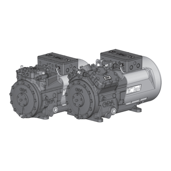
2| Product description 2.1 Short description • HA22e: Semi-hermetic two-cylinder reciprocating compressor with oil pump lubrication. • HA34e: Semi-hermetic four-cylinder reciprocating compressor with oil pump lubrication. • Air cooled drive motor. Transport eyelet Suction shut-off valve Valve plate Name plate... -
Page 7: Type Key
2| Product description Typschild (Beispiel) 2.2 Name plate (example) GEA Bock GmbH 72636 Frickenhausen, Germany HAX34e/315-4 AS35830A001 17,1/9,9 A 111A SE 55 Fig. 3 Typbezeichnung Spannung, Schaltung, Frequenz 50 Hz Maschinennummer Type designation Voltage, circuit, frequency Nenndrehzahl 50 Hz maximaler Betriebsstrom Machine number... -
Page 8: Areas Of Application
INFO For refilling, we recommend the above oil types. Alternatives: see lubricants table, Chapter 7.5 ATTENTION The oil level must be in the max. HA22e = visible part of the sight 0,7 Ltr. glass; damage to the com- oil level... - Page 9 3| Areas of application R404A/R507 Fig. 5 Fig. 6 Evaporation temperature (°C) Unlimited application range Condensing temperature (°C) Suction gas superheat (K) Reduced suction gas temperature Suction gas temperature (°C) Max. permissible operating Design for other pressure (LP/HP) : 19/28 bar areas on request LP = Low pressure HP = High pressure...
-
Page 10: Compressor Assembly
4| Compressor assembly INFO New compressors are factory-filled with inert gas. Leave this ser- vice charge in the compressor for as long as possible and prevent the ingress of air. Check the compressor for transport damage before starting any work. 4.1 Storage and transport Storage at (-30°C) - (+70°C), maximum permissible relative humidity 10% - 95%, no condensation Do not store in a corrosive, dusty, vaporous atmosphere or in a com- bustible environment. -
Page 11: Pipes
4| Compressor assembly The pipe connections have graduated inside diameters so that pipes with standart millimetre and inch dimensions can be used. The connection diameters of the shut-off valves are rated for maximum compressor output. The actual required pipe cross section must be matched to the output. The same applies for non-return valves. Fig. -
Page 12: Operating The Shut-Off Valves
4| Compressor assembly 4.6 Operating the shut-off valves Before opening or closing the shut-off valve, release the valve spindle seal by approx. ¼ of a turn counter-clockwise. After activating the shut-off valve, re-tighten the adjustable valve spindle seal clockwise. Release Tighten Valve spindle seal Fig. -
Page 13: Electrical Connection
5| Electrical connection DANGER Risk of electric shock! High voltage! Only carry out work when the electrical system is disconnected from the power supply! ATTENTION When attaching accessories with an electrical cable, a minimum bending radius of 3 x the cable diameter must be maintained for laying the cable. - Page 14 5.3 Circuit diagramm for direct start 230 V ∆ / 400 V Y FC1.1 I> I> I> FC1.1 L3 N PE -EC1 Θ B1 B2 INT69G Compressor terminal box Anschlußkasten Verdichter Fig. 13 Cold conductor (PTC sensor) motor winding Thermal protection thermostat (PTC sensor) Load circuit safety switches Control power circuit fuse High pressure safety monitor Safety chain (high/low pressure monitoring ) Main switch...
- Page 15 L1.1 L2.1 L3.1 L1.2 P> ˜ Θ Θ Release switch (thermostat) Control voltage switch Compressor motor Fan motor Compressor contactor INT69 G Electronic trigger unit INT69 G Oil sump heater...
-
Page 16: Electronic Trigger Unit Int69 G
5| Electrical connection 5.4 Electronic trigger unit INT69 G The compressor motor is fitted with cold conductor temperature sensors (PTC) connected to the electronic trigger unit INT69 G in the terminal box. In case of excess temperature in the motor winding, the INT69 G deactivates the motor contactor. -
Page 17: Start Unloader
Reset after mains on 11-14 5.7 Start unloader To avoid current peaks during the starting phase we recommend using the GEA Bock-ESS soft starting device (Electronic Soft Start). Refer to "Accessories" for further information. 5.8 Fan motor The fan motor for cooling the compressor is already wired in the terminal box. The power supply as well as triggering of the compressor contactor should be made in accordance with the basic circuit diagram (in the terminal box). The fan motor is protected by an internal temperature monitor. -
Page 18: Commissioning
6| Commissioning 6.1 Preparations for start-up INFO To protect the compressor against inadmissible operating conditions, high pressure and low pressure pressostats are mandatory on the installation side. The compressor has undergone trials in the factory and all functions have been tested. There are therefore no special running-in instructions. -
Page 19: Start-Up
6| Commissioning Make sure that the suction and pressure line shut-off valves are open. With the compressor switched off, add the liquid refrigerant directly to the condenser or receiver, breaking the vacuum. If the refrigerant needs topping up after starting the compressor, it can be topped up in vapour form on the suction side, or, taking suitable precautions, also in liquid form at the inlet to the evaporator. ATTENTION Avoid overfilling the system with refrigerant! To avoid shifts in concentration, zeotropic refrigerant blends (e.g. R407C) must always only be filled into the refrigerating plant in liquid form. -
Page 20: Maintenance
Dispose of used oil according to the regulations; observe national regulations. Annual checks: Oil level, leak tightness, running noises, pressures, temperatures, function of auxiliary devices such as oil sump heater, pressure switch. 7.3 Spare parts recommendation HA22e / ... 125-4 160-4 190-4 Designation Ref. -
Page 21: Accessories
7| Maintenance 7.4 Accessories Available accessories can be found on the Internet at www.gea.com 7.5 Extract from the lubricants table The oil type filled as standard in the factory is marked on the name plate . This oil type should be used as a preference. Alternatives are stated in the extract from our lubricants table below. Refrigerants GEA standard oil types Recommended alternatives... -
Page 22: Technical Data
8| Technical data Oil charge Weight 220-240 V ∆ / 380-420 V Y - 3 - 50 Hz 265-290 V ∆ / 440-480 V Y - 3 - 60 Hz No. of cylinders... - Page 23 8| Technical data Oil charge Weight 220-240 V ∆ / 380-420 V Y - 3 - 50 Hz 265-290 V ∆ / 440-480 V Y - 3 - 60 Hz No. of cylinders...
-
Page 24: Dimensions And Connections
9| Dimensions and connections HA22e Centre of gravity Vibration damper Dimensions in mm Fig. 16 Suction line see technical data, Chapter 8 Discharge line Connection suction side, not lockable 8 “ NPTF Connection suction side, lockable 16 “ UNF Connection discharge side, not lockable 8 “... - Page 25 9| Dimensions and connections HA34e Centre of gravity Vibration damper Dimensions in mm Fig. 17 Suction line see technical data, Chapter 8 Discharge line Connection suction side, not lockable 8 “ NPTF Connection suction side, lockable 16 “ UNF Connection discharge side, not lockable 8 “...
-
Page 26: Declaration Of Installation
(in accordance with Machinery Directive 2006/42/EC) The manufacturer: GEA Bock GmbH, Benzstraße 7 72636 Frickenhausen, Tel.: 07022/9454-0 hereby declares that the refrigerating compressor HA22e and HA34e complies with the basic requirements of Appendix II 1B of the Machinery Directive 2006/42/EC. Applied harmonised standard: EN 12693:2008 and the corresponding standards referenced A partly completed machine may only be put into operation when it has been established that the machine, into which the partly completed machine is to be installed, conforms to the r egulations of the Machinery Directive (2006/42/EC). -
Page 27: Service
The GEA service team can be contacted by phone with a toll-free hotline 00 800 / 800 000 88 or via e-mail: info@gea.com Yours faithfully GEA Bock GmbH Benzstraße 7 72636 Frickenhausen Germany... - Page 28 50 countries. Founded in 1881, the company is one of the largest providers of innovative equipment and process technology. GEA Group is listed in the STOXX ® Europe 600 index. GEA Bock GmbH Benzstraße 7 Phone +49 (0)7022 9454-0 info@gea.com...
Need help?
Do you have a question about the HA22e and is the answer not in the manual?
Questions and answers