Table of Contents
Advertisement
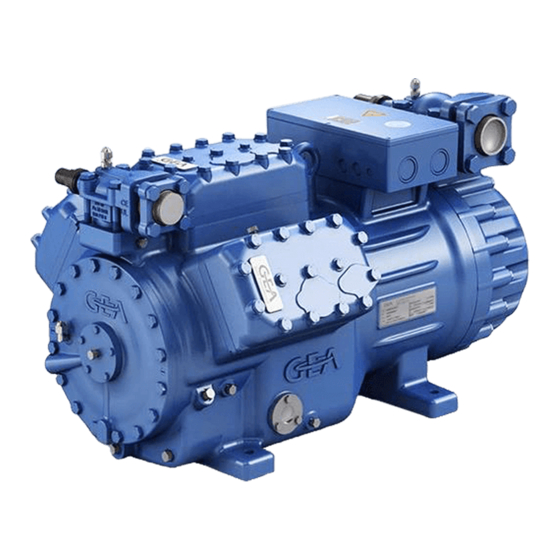
GEA Bock HG66e (HC/LG)
Assembly instructions
96446-09.2020-Gb
Translation of the original instructions
HG(X)66e/1340-4 (S)
HG(X)66e/1540-4 (S)
HG(X)66e/1750-4 (S)
HG(X)66e/2070-4 (S)
HGX66e/1340 ML 28 LG
HGX66e/1540 ML 34 LG
HGX66e/1750 ML 44 LG
HGX66e/2070 ML 50 LG
HG66e/1340-4 (S) HC
HG66e/1540-4 (S) HC
HG66e/1750-4 (S) HC
HG66e/2070-4 (S) HC
HGX66e/1340 S 35 LG
HGX66e/1540 S 40 LG
HGX66e/1750 S 50 LG
HGX66e/2070 S 60 LG
Advertisement
Table of Contents

Subscribe to Our Youtube Channel
Related Manuals for GEA Bock HG66e Series


Summary of Contents for GEA Bock HG66e Series
- Page 1 GEA Bock HG66e (HC/LG) Assembly instructions 96446-09.2020-Gb Translation of the original instructions HG(X)66e/1340-4 (S) HG66e/1340-4 (S) HC HG(X)66e/1540-4 (S) HG66e/1540-4 (S) HC HG(X)66e/1750-4 (S) HG66e/1750-4 (S) HC HG(X)66e/2070-4 (S) HG66e/2070-4 (S) HC HGX66e/1340 ML 28 LG HGX66e/1340 S 35 LG...
-
Page 2: Table Of Contents
Observe the safety instructions contained in these instructions. These instructions must be passed onto the end customer along with the unit in which the compres- sor is installed. Manufacturer GEA Bock GmbH 72636 Frickenhausen Contact GEA Bock GmbH Benzstraße 7... - Page 3 Contents Page Areas of application 4.1 Refrigerants 4.2 Oil charge 4.3 Limits of application Areas of application on HC and LG compressors 5.1 Refrigerants 5.2 Oil charge 5.3 Limits of application Compressor assembly 6.1 Storage and transport 6.2 Setting up 6.3 Pipe connections 6.4 Pipes 6.5 Start unloader (external) 6.6 Laying suction and pressure lines 6.7 Operating the shut-off valves 6.8 Operating mode of the lockable service connections 6.9 Suction pipe filter and filter drier...
-
Page 4: Safety
1| Safety 1.1 Identification of safety instructions: DANGER Indicates a dangerous situation which, if not avoided, will cause immediate fatal or serious injury. WARNING Indicates a dangerous situation which, if not avoided, may cause fatal or serious injury. CAUTION Indicates a dangerous situation which, if not avoided, may cause fairly severe or minor injury. ATTENTION Indicates a situation which, if not avoided, may cause property damage. INFO Important information or tips on simplifying work. 1.2 Qualifications required of personnel WARNING Inadequately qualified personnel poses the risk of accidents, the consequence being serious or fatal injury. Work on compressors is therefore reserved for personnel which is qualified to work on pressurized refrigerant systems: • For example, a refrigeration technician, refrigeration mechatronic engineer. As well as professions with comparable training, which enables personnel to assemble, install, maintain and repair refrigeration and air-conditioning systems. -
Page 5: General Safety Instructions
1| Safety 1.3 General safety instructions WARNING Risk of accidents. Refrigerating compressors are pressurised machines and as such call for heightened caution and care in handling. The maximum permissible overpressure must not be exceeded, even for testing purposes. Risk of burns! - Depending on the operating conditions, surface temperatures of over 60°C on the discharge side or below 0°C on the suction side can be reached. - Avoid contact with refrigerant necessarily. Contact with refrigerant can cause severe burns and skin damage. 1.4 Intended use WARNING The compressor may not be used in potentially explosive environments! These assembly instructions describe the standard version of the compressor named in the title man- ufactured by GEA. -
Page 6: Safety Instructions For Use Of Flammable Refrigerants
2 | Safety instructions for use of flammable refrigerants 2.1 Safety instructions DANGER • Explosion and fire risk! Hydrocarbons and synthetic HFO refrigerants are colourless, combustible gases which occur naturally and which are explosive in a certain blend! • Hydrocarbons are classified into the safety group A3 (highly- inflammable refrigerant) according to EN 378. -
Page 7: Product Description
3 | Product description 3.1 Short description • Semi-hermetic six-cylinder reciprocating compressor with suction-gas cooled drive motor. • The stream of refrigerant sucked out of the evaporator flows over the motor and cools it intensively. In this way, the motor can be kept at a relatively low temperature level, particularly under high loads. - Page 8 3 | Product description 3.2 Name plate (example) GEA Bock GmbH 72636 Frickenhausen, Germany 380-420 Y/YY HGX66e/2070-4 180,0 BB12345-A001 440-480 Y/YY 107,0 A Y: 196,0 A YY: 335,0 A 217,2 IP 65 SE 55 Fig. 2 Type designation Voltage, circuit, frequency 50 Hz...
-
Page 9: Type Key
3 | Product description 3.4 Type key HC compressor (example) 2070- Hydrocarbons Motor variant ² Number of poles Swept volume e-series Numbers of cylinders Size Series ¹ ¹ HG - Hermetic Gas-Cooled (suction gas-cooled) ² S - More powerful motor 3.5 Typ key LG compressor (example) 2070 HFO refrigerant Engine performance in HP... -
Page 10: Areas Of Application
4 | Areas of application 4 .1 Refrigerants • HFKW / HFC: R134a, R404A/R507, R407C, R407F • (H)FCKW / (H)CFC: R22 4.2 Oil charge The compressors are filled at the factory with the following oil type: - für R134a, R404A/R507, R407C, R407F FUCHS Reniso Triton SE 55 - für R22 FUCHS Reniso SP 46 Compressors with ester oil charge (FUCHS Reniso Triton SE 55) are marked with an X in the type designation (e.g. -
Page 11: Areas Of Application On Hc And Lg Compressors
4 | Areas of application Maximum admissible Maximum admissible operating LP = Low pressure frequency: 60 Hz pressure (LP/HP) : 19/28 bar HP = High pressure 5 | Areas of application at HC and LG compressors 5.1 Refrigerants • Hydrocarbons: R290, R1270 (Recommendation quality 2.5 (< 50 ppm H • HFO refrigerants: R1234ze, R1234yf, R455A, R454C 5.2 Oil charge The compressors are factory-charged with the following oil type: •... -
Page 12: Compressor Assembly
6 | Compressor assembly INFO New compressors are factory-filled with inert gas. Leave this service charge in the compressor for as long as possible and pre- vent the ingress of air. Check the compressor for transport damage before starting any work. 6.1 Storage and transport Storage at (-30°C) - (+70°C), maximum permissible relative humidity 10% - 95%, no condensation Do not store in a corrosive, dusty, vaporous atmosphere or in a com- bustible environment. -
Page 13: Pipe Connections
6 | Compressor assembly 6.3 Pipe connections ATTENTION Damage possible. Superheating can damage the valve. Remove the pipe supports from the valve for soldering. Only solder using inert gas to inhibit oxidation products (scale). The discharge gas connection can be moved upwards with an adapter (accessory). This makes it easier to remove the com- pressor from a refrigerating system. Pipe connections on the compressor are available for soldering or welding (accessories). The discharge and suction line valves have graduated inside diameters so that pipes with standard millimetre and inch dimensions can be used. The pipe will be immersed more or less deeply according to dimension. -
Page 14: Laying Suction And Pressure Lines
6 | Compressor assembly Solenoid valve dead Non-return valve open Fig. 6 Important: Start unloader may only be employed during the starting phase. Check the solenoid valve and the non-return valve regularly for tightness. In addition, we recommend to use a heat protection thermostat on the discharge side of the com- pressor. -
Page 15: Operating The Shut-Off Valves
6 | Compressor assembly 6.7 Operating the shut-off valves Before opening or closing the shut-off valve, release the valve spindle seal by approx. 1 / 4 of a turn counter-clockwise. After activating the shut-off valve, re-tighten the adjustable valve spindle seal clockwise. Release Tighten Valve spindle seal Fig. -
Page 16: Suction Pipe Filter And Filter Drier
6 | Compressor assembly 6.9 Suction pipe filter and filter drier For systems with long pipes and higher degree of contamination, a filter on the suction-side is recommended. The filter has to be be renewed depending on the degree of contamination (reduced pressure loss). Moisture in the refrigeration circuit can lead to crystal and hydrate formation. For this reason, we recommend using a filter drier and a sight glass with a moisture indicator. -
Page 17: Standard Motor, Design For Direct Or Partial Winding Start
7 | Electrical connection 7.2 Standard motor, design for direct or partial winding start Designation on the name plate Sticker on the terminal box Y/YY Y/YY Compressors with this marking are suitable for direct or partial winding start. The motor winding is subdivided into two parts: Part winding 1 = 50 % and part winding 2 = 50 %. This winding division reduces the start-up current needed for a part winding start to approx. - Page 18 7.3 Basic circuit diagram for part winding start with standard motor FC1.2 FC1.1 I> I> I> I> I> I> FC1.1 FC1.2 L3 N PE Y/YY B1 B2 INT69 Compressor terminal box Anschlußkasten Verdichter Fig. 12 High pressure safety monitor Safety chain (high/low pressure monitoring) Cold conductor (PTC sensor) motor winding Thermal protection thermostat (PTC sensor) Release switch (thermostat) Datum...
- Page 19 L1.1 L2.1 L3.1 L1.2 P> DANGER Explosion risk! Θ Electronic trigger Θ INT69 G at HC and LG Θ compressors has to be installed outside any danger area! See also chapter 7.9. DELTA- P II 6.c.8 FC1.1/1.2 Motor protection switch Control power circuit fuse INT69 G Electronic trigger unit INT69 G Delay relay for contactor switch over Main switch PW INT69 HG44/66...
-
Page 20: Special Motor: Design For Direct Or Star-Delta Start
7 | Electrical connection 5.4 Sondermotor: Ausführung für Direkt- oder Stern-Dreieck-Anlauf 5.4 Special motor: design for direct or star-delta start Für den Stern-Dreieck-Anlauf ist eine mechanische Anlaufentlastung mit Bypass-Magnetventil (Zubehör) erforderlich. A mechanical unloaded start with bypass solenoid valve is required for the star-delta start. Bezeichnung auf dem Typschild Aufkleber auf Klemmenkasten Designation on the name plate Sticker on the terminal box ∆... - Page 21 ∆ / Y ∆ / Y ∆ / Y 7 | Electrical connection Stern-Dreieck-Anlauf ist nur im Spannungsbereich ∆ (230 V) möglich. Beispiel: Stern-Dreieck-Anlauf ist nur im Spannungsbereich ∆ (230 V) möglich. Beispiel: Stern-Dreieck-Anlauf ist nur im Spannungsbereich ∆ (230 V) möglich. Beispiel: Star-delta start-up is only possible for ∆ (230 V) power supply. Example: 230 V ∆...
- Page 22 7.5 Basic circuit diagram for star-delta start 230 V ∆ / 400 V Y FC1.1 I> I> I> FC1.1 FC1.2 FC1.2 I> I> I> L3 N PE ˜ B1 B2 INT69G Compressor terminal box Anschlußkasten Verdichter Fig. 13 High pressure safety monitor Safety chain (high/low pressure monitoring) Cold conductor (PTC sensor) motor winding Thermal protection thermostat (PTC sensor) Release switch (thermostat) DELTA PII Oil differential pressure sensor DELTA-P II (accessory)
- Page 23 L1.1 L2.1 L3.1 L1.2 P> DANGER Explosion risk! Θ Electronic trigger Θ INT69 G at HC and LG Θ compressors has to be installed outside any danger area! See also chapter 7.9. DELTA- P II 6.b.7 6.b.8 6.b.8 Control power circuit fuse INT69 G Electronic trigger unit INT69 G Delay relay for contactor switch over Main switch Mains contactor...
-
Page 24: Electronic Trigger Unit Int69 G
7 | Electrical connection 7.6 Electronic trigger unit INT69 G The compressor motor is fitted with cold conductor temperature sensors (PTC) connected to the electronic trigger unit INT69 G in the terminal box. In case of excess temperature in the motor winding, the INT69 G deactivates the motor contactor. Once cooled, it can be restarted only if the electronic lock of the output relay (terminals B1+B2) is released by interrupting the supply voltage. - Page 25 7 | Electrical connection 7.8 Function test of the trigger unit INT69 G Before commissioning, after troubleshooting or making changes to the control power circuit, check the functionality of the trigger unit. Perform this check using a continuity tester or gauge. Relay position INT69 G Gauge state Relay position Deactivated state 11-12 INT69 G switch-on...
-
Page 26: Oil Sump Heater (Accessories)
7 | Electrical connection 7.10 Oil sump heater (accessories) When the compressor is at a standstill, refrigerant diffuses into the lubricating oil of the compressors housing, depending on pressure and ambient temperature. This reduces the lubricating capacity of the oil. When the compressor starts up, the refrigerant contained in the oil evaporates out through the reduction in pressure. The consequences can be foaming and migration of the oil, causing oil shocks under certain circumstances. -
Page 27: Capacity Regulator (Accessories) Ru
7 | Electrical connection 7.12 Capacity regulator (Accessories) ATTENTION A fuse (max. 3xlB in accordance with IEC 60127-2-1) corresponding to the rated current must be placed in front of every magnetic coil of the capacity regulator as short-circuit protection. The ra- ted voltage of the fuse must be equal to or greater than the rated voltage of the magnetic coil. The ability of the fuses to switch off must be greater than or equal to the maximum assumable short- circuit current at the installation location. 8 | Commissioning 8.1 Preparations for start-up INFO To protect the compressor against inadmissible operating conditions, high pressure and low pressure pressostats are mandatory on the installation side. The compressor has undergone trials in the factory and all functions have been tested. There are therefore no special running-in instructions. -
Page 28: Evacuation
8 | Commissioning 8.4 Evacuation ATTENTION Do not start the compressor if it is under vacuum. Do not apply any voltage - even for test purposes (must only be operated with r efrigerant). Under vacuum, the spark-over and creepage current distances of the terminal board connection bolts shorten; this can result in winding and terminal board damage. First evacuate the system and then include the compressor in the evacuation process. Relieve the compressor pressure. -
Page 29: Maintenance
8 | Commissioning 8.7 Avoiding slugging ATTENTION Slugging can damage the compressor and cause refrigerant to leak. To prevent slugging: The complete refrigeration system must be properly designed. All components must be compatibly rated with each other with regard to output (particularly the evaporator and expansion valves). Suction gas superheat at the compressor input should be min. 7 - 10 K. (check the setting of the expansion valve). -
Page 30: Extract From The Lubricants Table
9 | Maintenance 9.4 Extract from the lubricants table The oil type filled as standard in the factory is marked on the name plate . This oil type should be used as a preference. Alternatives are stated in the extract from our lubricants table below. Do not mix oils with each other, use only one type of oil. Refrigerants Bock standard oil types Recommended alternatives Fuchs Reniso Triton SEZ 32 Esso/Mobil EAL Arctic 46 (e.g. R134a, R407C, Fuchs Reniso Triton SE 55 Sunoco Suniso SL 46 R404A) -
Page 31: Accessories
10 | Accessories 10.1 Capacity regulator ATTENTION If the capacity regulator is installed at the factory, the control component (pilot valve) is subsequently installed and connected by the customer. LR 1 LR 2 Delivery condition 1 (from the factory): Fig. 19 Fig. 18 Cylinder cover prepared for capacity regulator. Cover Fig. 21 Fig. 20 Before start-up, remove the cover at the Delivery condition 2 (from the factory): capacity regulator and replace it with the... -
Page 32: Oil Separator
10 | Accessories WARNING Several capacity regulators cannot switch at the same time during compressor operation! Otherwise the sudden change in load can damage the compressor! Comply with the switching interval of 60 s. • Comply with the switching sequence: Switching on Switching off ATTENTION Capacity-regulated operation alters the gas speeds and pressure r atios of the refrigerating plant: Adjust the suction line routing and dimensioning accordingly, do not set the control intervals too close and do not let the system switch more than 12 times per hour (refrigerating plant must have reached a state of equilibrium). Continuous operation in the control stage is not recommended as the gas velocity in the plant system under certain circumstances does not guarantee sufficient oil return to the compressor with activated capacity regulator. W e recommend switching to unregulated operation (100% capac- ity) for at least 5 minutes per capacity-regulated operating hour. An assured oil return can also be realised by a 100% capacity requirement after each compressor restart. E lectrical actuation of the solenoid valve: Normally open, (corre- sponds to 100 % compressor capacity). Special accessories are only pre-mounted in the factory if ordered specially by customer. Retrofitting is possible in full compliance with the safety instructions and repair instructions enclosed with the kits. -
Page 33: Oil Level Regulator
10 | Accessories 10.3 Oil level regulator Oil level regulation systems have proven themselves with parallel circuits of several compressors. The connection "0" is provided for installing an oil level regulator (see dimensions drawing). All common mechanical oil level regulators from AC&R, ESK, Carly as well as the electronic oil level regulation system from AC&R, Teklab, OM3 TraxOil from Alco and ESK (only long version) can be connected directly without adapters (see fig.23). -
Page 34: Technical Data
11 | Technical data Oil charge (sight glass centre) Oil charge (ex works) Suction line Discharge line Weight Starting current (rotor locked) Max. power consumption Max. operating current 380-420 V Y/YY - 3 - 50 Hz PW 440-480 V Y/YY - 3 - 60 Hz PW Voltage PW = Part Winding Winding ratio : 50 % / 50 % Displacement (1450 / 1740 rpm) -
Page 35: Dimensions And Connections
12 | Dimensions and connections Centre of gravity H,D1 Anschlüsse / Connections Saugabsperrventil Suction line valve, Druckabsperrventi Discharge line valv Anschluss Saugse Connection suction Anschluss Saugse Connection suction Anschluss Druckse Connection discha Anschluss Druckse Connection discha HG66e/ Anschluss Öldruck Anschlüsse / HG66e/ 1340-4 (S) Connection oil pre... - Page 36 10| Dimensions and connections Suction line see technical data, chapter 11 Discharge line Connection suction side, not lockable “ NPTF 7 / 16 Connection suction side, lockable “ UNF 1 / 8 Connection discharge side, not lockable “ NPTF 7 / 16 Connection discharge side, lockable “...
-
Page 37: Declaration Of Incorporation
13 | Declaration of incorporation Declaration of incorporation for incomplete machinery in accordance with EC Machinery Directive 2006/42/EC, Annex II 1. B Manufacturer: GEA Bock GmbH Benzstraße 7 72636 Frickenhausen, Germany We, as manufacturer, declare in sole responsibility that the incomplete machinery... - Page 38 14 | Service Dear customer, Bock compressors are top-quality, reliable and service-friendly quality products. If you have any questions about installation, operation and accessories, please contact our technical service or specialist wholesaler and/or our representative. The Bock service team can be contacted by phone, +49 (0)7022 9454-0 or via gea.com/contact Yours faithfully GEA Bock GmbH Benzstraße 7 72636 Frickenhausen Germany...
- Page 40 50 countries. Founded in 1881, the company is one of the largest providers of innovative equipment and process technology. GEA Group is listed in the STOXX ® Europe 600 index. GEA Bock GmbH Benzstraße 7 Phone +49 (0)7022 9454-0 gea.com/contact...
Need help?
Do you have a question about the HG66e Series and is the answer not in the manual?
Questions and answers