
Subscribe to Our Youtube Channel
Related Manuals for GEA Bock Bock HA5


Summary of Contents for GEA Bock Bock HA5
- Page 1 GEA Bock HA5 Assembly instructions 09911-11.2015-Gb Translation of the original instructions HA5/725-4 HAX5/725-4 HA5/830-4 HAX5/830-4 HA5/925-4 HAX5/925-4...
- Page 2 Observe the safety instructions contained in these instructions. These instructions must be passed onto the end customer along with the unit in which the compres- sor is installed. Manufacturer GEA Bock GmbH 72636 Frickenhausen Contact GEA Bock GmbH Benzstraße 7...
-
Page 3: Table Of Contents
Contents Page Safety 1.1 Identification of safety instructions 1.2 Qualifications required of personnel 1.3 General safety instructions 1.4 Intended use Product description 2.1 Short description 2.2 Name plate 2.3 Type key Areas of application 3.1 Refrigerants 3.2 Oil charge 3.3 Limits of application Compressor assembly 4.1 Storage and transport 4.2 Setting up 4.3 Pipe connections 4.4 Pipes... -
Page 4: Safety
Contents Page Technical data Dimensions and connections Declaration of installation Service 1| Safety 1.1 Identification of safety instructions: Indicates a dangerous situation which, if not DANGER! avoided, will cause immediate fatal or serious injury. Indicates a dangerous situation which, if not avoided, may cause fatal or serious injury. WARNING! Indicates a dangerous situation which, if not avoided, may cause fairly severe or minor injury. CAUTION! Indicates a situation which, if not ATTENTION! avoided, may cause property damage. INFO! Important information or tips on simplifying work. 1.2 Qualifications required of personnel WARNING! I nadequately qualified personnel poses the risk of accidents, the consequence being serious or fatal injury. Work on compressors must therefore only be performed by personnel with the qualifica- tions listed below:... -
Page 5: General Safety Instructions
1| Safety 1.3 General safety instructions WARNING! • Refrigerating compressors are pressurised machines and t herefore require particular caution and care in handling. • Risk of burns! Depending on the operating conditions, surface temperatures of over 60 °C on the pressure side or below 0 °C on the suction side can be reached. • The maximum permissible overpressure must not be exceeded, even for testing purposes. 1.4 Intended use These assembly instructions describe the standard version of the HA5 manufactured by GEA. -
Page 6: Product Description
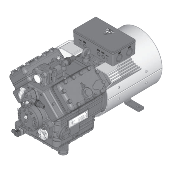
2| Product description 2.1 Brief description • Semi-hermetic four-cylinder reciprocating compressor with oil pump lubrication. • Flange-mounted drive motor on the compressor case. • Specially or deep cooling with air-cooled motor and direct suction at the cylinder. Terminal box Air guide hood Transport eyelet with fan Suction shut-... -
Page 7: Type Key
2| Product description 2.2 Name plate (example) GEA Bock GmbH 72636 Frickenhausen, Germany HAX5/945-4 AS12345-001 26,0 A SE 55 Fig. 2 Type designation Voltage, circuit, frequency 50 Hz Machine number Nominal rotation speed maximum operating current Displacement Starting current (rotor blocked) Voltage, circuit, frequency 60 Hz Y: Part winding 1... -
Page 8: Areas Of Application
3| Areas of application 3.1 Refrigerants • HFKW / HFC: R404A/R507 • (H)FCKW / (H)CFC: 3.2 Oil charge The compressors are filled at the factory with the following oil type: - for R404A/R507 FUCHS Reniso Triton SE 55 - for R22 FUCHS Reniso SP 46 Compressors with ester oil charge (FUCHS Reniso Triton SE 55) are marked with an X in the type designation (e.g. - Page 9 3| Areas of application R404A R507 Fig. 4 Fig. 5 Unlimited Evaporation temperature (°C) application range Condensing temperature (°C) Reduced suction gas Suction gas superheat (K) temperature Suction gas temperature (°C) Max. permissible operating Design for other pressure (LP/HP) : 19/28 bar areas on request LP = Low pressure HP = High pressure...
-
Page 10: Compressor Assembly
4| Compressor assembly INFO! New compressors are factory-filled with inert gas (3 bar nitrogen). Leave this service charge in the compressor for as long as possible and prevent the ingress of air. Check the compressor for transport damage before starting any work. 4.1 Storage and transport Storage at (-30°C) - (+70°C), maximum permissible relative humidity 10% - 95%, no condensation Do not store in a corrosive, dusty, vaporous atmosphere or in a com- bustible environment. -
Page 11: Pipe Connections
4| Compressor assembly 4.3 Pipe connections ATTENTION! Superheating can damage the valve. Remove the pipe supports from the valve for soldering. Only solder using inert gas to inhibit oxidation products (scale). The pipe connections have graduated inside diameters so that pipes with standart millimetre and inch dimensions can be used. The connection diameters of the shut-off valves are rated for maximum compressor output. -
Page 12: Operating The Shut-Off Valves
4| Compressor assembly 4.6 Operating the shut-off valves Before opening or closing the shut-off valve, release the valve spindle seal by approx. ¼ of a turn counter-clockwise. After activating the shut-off valve, re-tighten the adjustable valve spindle seal clockwise. Release Tighten Valve spindle seal Fig. -
Page 13: Electrical Connection 13 Gb
5| Electrical connection Electrical connection DANGER! H igh voltage! Risk of electric shock! Only carry out work when the electrical system is disconnected from the power supply! ATTENTION! When attaching accessories with an electrical cable, a minimum bending radius of 3 x the cable diameter must be maintained for laying the cable. INFO! Connect the compressor motor in accordance with the circuit diagram (see inside of terminal box). Use suitable cable entry point of the correct protection type (see name plate) for routing cables into the terminal box. -
Page 14: Basic Circuit Diagram For Part Winding Start With Standard Motor
5.3 Basic circuit diagram for part winding start with standard motor 0 1 2 3 4 F1.2 F1.1 I=33% I=66% F1.1 F1.2 XSS Y/YY X1 L1 L1 N N 43 43 11 MP10 X2 1 Compressor terminal box AnschluákastenVerdichter Fig. 17 Cold conductor (PTC sensor) motor winding Thermal protection thermostat (PTC sensor) Datum 02.Feb.2009 Bearb. - Page 15 5 6 7 8 9 L1.1 L2.1 L3.1 L1.2 P> P< M1.1 P™l Main switch Compressor motor PWMP10 M1.1 Fan motor BOCKCOMPRESSORS Mains contactor (part winding 1) Mains contactor (part winding 2) Delay relay max. 1s Control voltage switch Oil sump heater...
- Page 16 5| Electrical connection The motor is wired for direct start (YY) at the factory. For part winding start Y / YY, the bridges must be removed and the motor feed line connected according to the circuit diagram: 400 V Direktstart YY Teilwicklungsstart Y/YY Direct start YY Part winding start Y/YY...
-
Page 17: Special Motor: Design For Direct Or Star-Delta Start
5| Electrical connection 5.4 Sondermotor: Ausführung für Direkt- oder Stern-Dreieck-Anlauf 5.4 Sondermotor: Ausführung für Direkt- oder Stern-Dreieck-Anlauf 5.4 Sondermotor: Ausführung für Direkt- oder Stern-Dreieck-Anlauf 5.4 Special motor: design for direct or star-delta start Für den Stern-Dreieck-Anlauf ist eine mechanische Anlaufentlastung mit Bypass-Magnetventil Für den Stern-Dreieck-Anlauf ist eine mechanische Anlaufentlastung mit Bypass-Magnetventil Für den Stern-Dreieck-Anlauf ist eine mechanische Anlaufentlastung mit Bypass-Magnetventil (Zubehör) erforderlich. - Page 18 5.5 Basic circuit diagram for star-delta start with special motor 0 1 2 3 4 F1.1 F1.1 F1.2 F1.2 XSS Net400V50Hz X1 L1 L1 N N 43 43 11 X2 1 2 MP10 Compressor terminal box AnschluákastenVerdichter Fig. 18 Cold conductor (PTC sensor) motor winding Thermal protection thermostat (PTC sensor) F1.1 /1.2 2 motor protection switches Control power circuit fuse...
- Page 19 5 6 7 8 9 L1.1 L2.1 L3.1 L1.2 P> P< M1.1 P™l Compressor motor M1.1 Fan motor Mains contactor Δ-contactor Y-contactor Delay relay S/D changeover MP10 BOCKCOMPRESSORS Delay relay, start unloader Control voltage switch Start unloader Oil sump heater...
-
Page 20: Electronic Trigger Unit Mp
5| Electrical connection 5.6 Electronic trigger unit MP 10 The compressor motor is fitted with cold conductor temperature sensors (PTC) connected to the electronic trigger unit MP 10 in the terminal box. Readiness to operate is signalled by the H3 LED (green) after the power supply is applied. - Page 21 5| Electrical connection 5.8 Function test of the trigger unit MP 10 Before start-up, troubleshooting or making changes to the control power circuit, check the functionality of the trigger unit: LED H1 LED H2 LED H3 Procedure green • Interrupt power supply (L1 or S1) • Release the motor temperature sensor connection (1 or 2) •...
-
Page 22: Oil Sump Heater (Accessories)
5| Electrical connection 5.9 Oil sump heater (accessories) During compressor standstill and depending on the pressure and ambient temperature, refrigerant diffuses into the compressor's lubricating oil. This reduces the oil's lubricating ability. When the compressor is started, the refrigerant contained in the oil evaporates due to the decline in pressure. This can result in oil foaming and oil exodus which can result in oil hammer in certain circumstances. -
Page 23: Commissioning
6| Commissioning 6.1 Preparations for start-up INFO! I n order to protect the compressor against inadmissible operating conditions, high-pressure and low-pressure pressostats controls are mandatory on the installation side. The compressor has undergone trials in the factory and all functions have been tested. There are therefore no special running-in instructions. Check the compressor for transport damage! 6.2 Pressure strength test The compressor has been tested in the factory for pressure integrity. - Page 24 6| Commissioning 6.5 Refrigerant filling CAUTION! Wear personal protective clothing such as goggles and protective gloves! Make sure that the suction and pressure line shut-off valves are open. With the compressor switched off, add the liquid refrigerant directly to the condenser or receiver, breaking the vacuum. If the refrigerant needs topping up after starting the compressor, it can be topped up in vapour form on the suction side, or, taking suitable precautions, also in liquid form at the inlet to the evaporator.
-
Page 25: Connection Of Oil Level Regulator
6| Commissioning 6.8 Connection of oil level regulator Oil level regulation systems have proven themselves with parallel circuits of several compressors. The connection "0" is provided for installing an oil level regulator (see dimensions drawing). All common oil level regulators from AC&R, ESK and Carly as well as the OM3 TraxOil oil level regulation system from Alco can be connected directly without adapters (see Fig. -
Page 26: Accessories
7| Maintenance 7.3 Recommended spare parts HA5 / ... 725-4 830-4 925-4 Ref. No. Ref. No. Ref. No. Designation Set of gaskets 08961 Valve plate kit 08851 Oil pump kit 08384 Oil sump heater kit 08426 230 V ~ Only use genuine GEA spare parts! 7.4 Accessories Available accessories can be found on the Internet at www.gea.com 7.5 Extract from the lubricants table... - Page 27 8| Technical data Oil charge 380-420 V Y/YY - 3 - 50 Hz PW 440-480 V Y/YY - 3 - 60 Hz PW PW = Part Winding Winding ratio : 66% / 33% No. of cylinders...
- Page 28 9| Dimensions and connections ca.435 Centre of gravity DV B A1 N B SV Ansicht X: Anschlußmöglichkeit für Ö Ansicht X: Anschlußmöglichkeit für Ö View X: Possibility of connection of o View X: Possibility of connection of o Vue X : Raccord pour régulateur de n Vue X : Raccord pour régulateur de n ÖV ca.260...
- Page 29 9| Dimensions and connections Suction line see technical data, Chapter 8 Discharge line Connection suction side, not lockable 8 “ NPTF Connection suction side, lockable 16 “ UNF Connection discharge side, not lockable 8 “ NPTF Connection discharge side, lockable 16 “...
- Page 30 European Union (in accordance with Machinery Directive 2006/42/EC) The manufacturer: GEA Bock GmbH, Benzstraße 7 72636 Frickenhausen, Tel.: 07022/9454-0 hereby declares that the refrigerating compressor HA5 complies with the basic requirements of Appendix II 1B of the Machinery Directive 2006/42/EC.
- Page 31 11| Service Dear customer, GEA compressors are top-quality, reliable and service-friendly quality products. If you have any questions about installation, operation and accessories, please contact our technical service or specialist wholesaler and/or our representative. The GEA service team can be contacted by phone with a toll-free hotline 00 800 / 800 000 88 or via e-mail: info@gea.com Yours faithfully GEA Bock GmbH Benzstraße 7 72636 Frickenhausen Germany...
- Page 32 50 countries. Founded in 1881, the company is one of the largest providers of innovative equipment and process technology. GEA Group is listed in the STOXX ® Europe 600 index. GEA Bock GmbH Benzstraße 7 Phone +49 (0)7022 9454-0 info@gea.com...
Need help?
Do you have a question about the Bock HA5 and is the answer not in the manual?
Questions and answers