Table of Contents
Advertisement
GEA Bock EX-HG66e
Assembly instructions
96463-08.2019-Gb
Translation of the original instructions
EX-HG66e/1340-4
EX-HG66e/1540-4
EX-HG66e/1750-4
EX-HG66e/2070-4
EX-HG66e/1340-4 S
EX-HG66e/1540-4 S
EX-HG66e/1750-4 S
EX-HG66e/2070-4 S
Device category 2 G
acc. to directive 2014/34/EU
EX-HGX66e/1340-4
EX-HGX66e/1540-4
EX-HGX66e/1750-4
EX-HGX66e/2070-4
EX-HGX66e/1340-4 S
EX-HGX66e/1540-4 S
EX-HGX66e/1750-4 S
EX-HGX66e/2070-4 S
EX-HG66e/1340-4 HC
EX-HG66e/1540-4 HC
EX-HG66e/1750-4 HC
EX-HG66e/2070-4 HC
EX-HG66e/1340-4 S HC
EX-HG66e/1540-4 S HC
EX-HG66e/1750-4 S HC
EX-HG66e/2070-4 S HC
Advertisement
Table of Contents

Related Manuals for GEA Bock EX-HG66e Series


Summary of Contents for GEA Bock EX-HG66e Series
- Page 1 GEA Bock EX-HG66e Assembly instructions Device category 2 G acc. to directive 2014/34/EU 96463-08.2019-Gb Translation of the original instructions EX-HG66e/1340-4 EX-HGX66e/1340-4 EX-HG66e/1340-4 HC EX-HG66e/1540-4 EX-HGX66e/1540-4 EX-HG66e/1540-4 HC EX-HG66e/1750-4 EX-HGX66e/1750-4 EX-HG66e/1750-4 HC EX-HG66e/2070-4 EX-HGX66e/2070-4 EX-HG66e/2070-4 HC EX-HG66e/1340-4 S EX-HGX66e/1340-4 S EX-HG66e/1340-4 S HC...
-
Page 2: Table Of Contents
Observe the safety instructions contained in these instructions. These instructions must be passed onto the end customer along with the unit in which the compressor is installed. Manufacturer GEA Bock GmbH 72636 Frickenhausen Contact GEA Bock GmbH Benzstraße 7... - Page 3 Contents page Compressor assembly 4.1 Ignition source control of the compressor 4.2 Storage and transport 4.3 Setting up 4.4 Pipe connections 4.5 Pipes 4.6 Laying suction and pressure lines 4.7 Operating the shut-off valves 4.8 Operating mode of the lockable service connections 4.9 Suction pipe filter Electrical connection 5.1 Potential equalization...
-
Page 4: Safety
1 | Safety 1.1 Identification of safety instructions: DANGER Indicates a dangerous situation which, if not avoided, will cause immediate fatal or serious injury. WARNING Indicates a dangerous situation which, if not avoided, may cause fatal or serious injury. CAUTION Indicates a dangerous situation which, if not avoided, may cause fairly severe or minor injury. -
Page 5: Safety Instructions
1 | Safety 1.3 Safety instructions WARNING • Refrigerating compressors are pressurised machines and there- fore require particular caution and care in handling. • Risk of burns! Depending on the operating conditions, surface temperatures of over 60 °C on the pressure side or below 0 °C on the suction side can be reached. -
Page 6: Intended Use
1 | Safety 1.4 Intended use These assembly instructions describe the compressors named in the title manufactured by GEA. The compressor is intended for use in refrigeration systems inside explosion-endangered areas under the designation specified on the name plate in accordance with the European ATEX Directives. Use of the specified refrigerants as well as observance of the operating limits and listed stand- ards must be ensured in any case. -
Page 7: Product Description
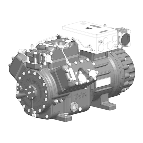
2 | Product description 2.1 Short description • Semi-hemetic six-cylinder reciprocating compressor with oil pump lubrication. • For use in explosion-endangered areas. Transport eyelet Potential Discharge equalization shut-off valve Name plate Oil pump Oil sight glass Fig. 1 Terminal box Valve plate Suction shut-off... - Page 8 2 | Product description 2.2 Ignition protection concept In accordance with Directive 2014/34/EU, GEA ATEX compressors are suitable for use in device category 2 for explosive gas atmospheres up to temperature class T3 and explosion hazard subgroup IIB / IIC. The entire compressor, including motor, is perceived as technically tight and therefore does not need an ignition protection.
- Page 9 2 | Product description Accessories Heating elements for the compressors to protect against explosion risks are designed in the pro- tection types increased safety (Ex d) and have to have to be mounted stationary at the designated areas in the compressor housing. The heating elements can be operated without temperature- and oil level control since the thermal type testing by the manufacturer verified that the heating elements prevent the exceeding of the temperature class of the compressor.
-
Page 10: Type Key
2 | Product description 2.3 Name plate (example) (GII 2G Ex de ia mb IIC TJ Gb / EPS 17 ATEX 1002 X GEA Bock GmbH Ex de ia mb IIC TJ Gb / IECEx EPS 17.0001 X -1""- �... -
Page 11: Atex Identification / Iecex Identification
2 | Product description 2.5 ATEX identification / IECEx identification Ex d e IIB/IIC T3 Gb Equipment protection level Temperature class T3 (max. 200 °C) Explosion subgroups, IIB = Offshore paint finish IIC = ESD paint finish Encapsulation, magnetic coil (option) Intrinsically safe equipment Increased safety Flameproof enclosure, heater (option) Europ. explosion protection acc. to Direc. 2014/34/EU Suitability for gas-explosive area Device category 2 (= zone 1) Explosion group II for Ex-endangered areas (not underground buildings) - Page 12 2 | Product description ATEX approval type IECEx approval type EPS 17 ATEX 1002 X / IECEx EPS 17.0001 X Special conditions: see "Conditions of Certification" Year of test/Test report number Bureau Veritas Consumer Products Services Germany GmbH International explosion protection Special conditions: see point 17 of the EC type examination certificate Test report number ATmospheres EXplosibles european explosion protection Year of test Bureau Veritas...
-
Page 13: Areas Of Application
3 | Areas of application 3.1 Approved refrigerant • HFKW / HFC: R134a, R404A, R507, R407C • (H)FCKW / (H)CFC: • Hydrocarbons : R290, R1270 INFO Used refrigerants have to have a self-ignition temperature of > 250 °C. 3.2 Important information on the use of hydrocarbons Hydrocarbons (combustible refrigerants) may be used in the compressors named in the title only if all relevant and applicable regulations, standards and technical rules are followed. -
Page 14: Oil Charge
3 | Areas of application 3.3 Oil charge The following oil grades are approved for the compressor: Refrigerant Oil grade FUCHS Reniso SP 46 R134a, R404A, R507, R407C FUCHS Reniso Triton SE 55 R290, R1270 FUCHS Reniso Synth 68 INFO Used refrigerant oils have to have a self-ignition temperature of >... -
Page 15: Limits Of Application
3 | Areas of application 3.4 Limits of application ATTENTION Compressor operation is possible within the operating limits. These can be found in GEA Bock compressor selection tool (VAP) under vap.gea.com. Observe the information given there. - Max. permissible discharge end temperature 140 °C. -
Page 16: Compressor Assembly
4 | Compressor assembly INFO • New compressors are factory-filled with inert gas. Leave this ser- vice charge in the compressor for as long as possible and prevent the ingress of air. • Check the compressor for transport damage before starting any work. -
Page 17: Storage And Transport
4 | Compressor assembly 4.2 Storage and transport Storage at (−30 °C) - (+70 °C), maximum permissible relative humid- ity 10 % - 95 %, no condensation Do not store in a corrosive, dusty, vaporous atmosphere or in a com- bustible environment. Fig. 5 Use transport eyelet. Do not lift manually! Use lifting gear! Fig. -
Page 18: Pipe Connections
4 | Compressor assembly 4.4 Pipe connections The pressure and suction shut-off valves have graduated inside di- ameters so that pipes in the common millimeter and inch dimensions can be used. The pipe will be inserted more or less deep, depending on the dimension. -
Page 19: Laying Suction And Pressure Lines
4 | Compressor assembly 4.6 Laying suction and pressure lines ATTENTION Improperly installed pipes can cause cracks and tears which can result in a loss of refrigerant INFO Proper layout of the suction and pressure lines directly after the compressor is integral to the smooth running and vibration behav- iour of the system. -
Page 20: Operating Mode Of The Lockable Service Connections
4 | Compressor assembly 4.8 Operating mode of the lockable service connections Service connection closed Pipe connection Spindle Connection blocked Compressor Fig. 16 Opening the shut-off valve: Spindle: turn to the left (counter-clockwise) as far as it will go. —> Shut-off valve completely opened / service connection closed. Service connection opened Pipe connection... -
Page 21: Electrical Connection
5 | Electrical connection Electrical connection DANGER Risk of electric shock! High voltage! Only carry out work when the electrical system is disconnected from the power supply! ATTENTION When attaching accessories with an electrical cable, a minimum bending radius of 3 x the cable diameter must be maintained for laying the cable. -
Page 22: Potential Equalization
5 | Electrical connection 5.1 Potential equalization Before start-up, the potential equalisation must be connected (see Fig. 18). INFO Special attention must be paid to sufficient conductivity of all con- tact points. There must be a large seat (e.g. with ring cable lug). The installed voltage equalization must be secured against loosing and firmly connected to earth. -
Page 23: Connection Of The Drive Motor
5 | Electrical connection - A t ambient temperatures > 40 °C, supply lines and cable / line bushings with a temperature resistance of at least 90 °C must be used. - The interpretation of the minimum terminal cross sections refer to the voltage range of 400 V, 50 Hz at 30 °C ambient temperature. - Page 24 5.5 Circuit diagrams for power section Legend for circuit diagram YY (direct start) Power section Main switch Performance contactor direct start FC1.1 Motor safety switch EC1 Compressor motor PTC-sensor motor winding Thermal protection thermostat UC1 Terminal box compressor X KK Terminal strip in terminal box compressor X SS Terminal strip in external switch cabinet Legend for circuit diagram Y / YY (part-winding start)
- Page 25 FC1.1 FC1.1 FC1.2 I> I> I> I> I> I> I> I> I> XKK D 1 XKK PW 1 / 1.b.4 / 1.b.9 XKK D 2 XKK PW 2 / 1.b.4 / 1.b.9 XKK D 3 XKK PW 3 / 1.b.4 / 1.b.9 XKK D 4 XKK PW 4...
- Page 26 5.6 Circuit diagrams for control section for direct start Legend for circuit diagram YY (direct start) FC1.1 Motor safety switch FC2.1 Control fuse FC2.2 Control fuse LR / oil sump heater Control voltage O/I Performance contactor direct start Collective malfunction alarm contactor KF4 ² Electronic trigger unit INT69 EX2 AC-double barrier (compression temperature) BT3¹ Pump down- pressostat / thermostat or external enabling switch BP1/BP2¹ High / low pressure monitoring in accordance with the relevant national regulations X SS Terminal strip in the external switch cabinet...
- Page 27 INT69 EX2 FC2.1 FC2.2 Δ XKK D 1 XKK D 2 Externe External release LR Freigabe LR FC1.1 4 PA XKK D 3 XKK D 4 Max. 90sec Potentialfrei Voltage-free Störung Safety Sicherheitskette chain fault P< P> P oil P-öl Kriwan Kriwan The circuit diagram is a system scheme for assignment and order of the safety chain, without...
- Page 28 5.7 Circuit diagrams for control section Y / YY part winding start Legend for circuit diagram Y / YY (part-winding-start) FC1.1 Motor safety switch FC1.2 Motor safety switch FC2.1 Fuse control FC2.2 Fuse control LR / oil sump heater SF1 Control voltage O/I Performance contactor part winding I Performance contactor part winding II KF3 Collective malfunction alarm contactor...
- Page 29 FC2.1 FC2.2 INT69 EX2 Δ FC1.1 XKK PW 1 max 90s XKK PW 2 FC1.2 Externe External release LR Freigabe LR 4 PA XKK PW 3 max 90s XKK PW 4 max 1s Voltage-free Potentialfrei or br P< P> P oil P-öl Kriwan Kriwan...
-
Page 30: Electronic Trigger Unit Int69 G Ex
5 | Electrical connection 5.8 Electronic trigger unit INT69 EX2 ATTENTION Install INT69 EX2 outside the explosion-endangered area. The INT69 EX2 trigger unit must be installed according to the wiring diagram. The hot gas sensors of the cylinder cover and the temperature sensors of the motor are observed by the electronic trigger unit INT69 EX2. - Page 31 5 | Electrical connection 5.9 Connection of the trigger unit INT69 EX2 Wire the PTC temperature sensor of the compressor motor, thermal protection thermostats of the cylinder cover, pressure and temperature monitoring of the system according to the wiring diagram (fig. 20+21). Pay attention to the PTC sensor connection. Terminals 1 + 2 on the trigger unit INT69 EX2 and terminals PTC 1 and PTC 2 on the compressor terminal board must not come into contact with mains voltage.
-
Page 32: Verification Of The Intrinsic Safety Of The Ptc Hot Gas Sensor
5 | Electrical connection 5.11 Verification of the intrinsic safety of the PTC hot gas sensor To verify the intrinsic safety of the hot gas sensor, the following values must be rated: Thermal protection thermostat (Art. No. 50159) Conditions for intrinsic safety [ V ] ≤... -
Page 33: Commissioning Gb
6 | Commissioning WARNING All of the following work must be performed only by qualified personnel (see page 4) and with exclusion of an explosive atmos- phere. 6.1 Preparations for start-up INFO In order to protect the compressor against prohibited operating conditions, high- and low-pressure monitors are necessary in accordance with the relevant national regulations! The compressor has undergone trials in the factory and all functions have been tested. -
Page 34: Evacuation
6 | Commissioning 6.4 Evacuation ATTENTION Do not start the compressor if it is under vacuum. Do not apply any voltage - even for test purposes (must only be operated with refrigerant). Under vacuum, the spark-over and creepage current distances of the terminal board connection bolts shorten;... -
Page 35: Start-Up
6 | Commissioning 6.6 Start-up WARNING Ensure that both shut-off valves are open before starting the compressor! Check that the safety and protection devices (pressure switch, motor protection, electrical contact protection measures, etc.) are functioning properly. Switch on the compressor and let it run for at least 10 minutes. Check the oil level: The oil must be visible in the sight glass. ATTENTION If larger quantities of oil have to be topped up, there is a risk of oil impact effects. -
Page 36: Maintenance
7 | Maintenance 7.1 Preparation WARNING All work must be performed only by: qualified personnel (see page 4) with exclusion of any danger of explosion. Before starting any work on the compressor: Obtain written work release. Switch off the compressor and secure it to prevent a restart. Relieve compressor of system pressure. -
Page 37: Spare Part Recommendation
7 | Maintenance 7.3 Spare part recommendation EX-HG66e / ... 1340-4 (S) 1540-4 (S) 1750-4 (S) 2070-4 (S) Designation Item No. Item No. Item No. Item No. Set of gaskets 81932 81933 81934 81935 Set of valve plate 81977 81978 81979 81980 Set of oil pump... -
Page 38: Accessories
8| Accessories 8.1 Capacity regulation (retrofit kit item no. 81443) By means of one or two capacity regulators the compressor output can be reduced to 66 % resp. 33 %. The capacity regulation works on a cylinder bank. It is necessary to replace the respective cylinder cover (included in the kit) for retrofitting. -
Page 39: Oil Sump Heater
8| Accessories 8.2 Oil sump heater (retrofit kit item no. 81401) The explosion-protected heating element is supplied as PTC heating element in a flameproof enclosure (Ex d) and is supplied with an electrical supply line of approx. 3.2 metres. Electrical wiring within the potentially explosive area could be though the terminal box compressor. The connection line for the heating element must be laid permanently and mechanically protected. During assembly and installation, the requirements of EN 60079-14 and EN 60079-17 must be observed. -
Page 40: Oil Differential Pressure Sensor Int250 Ex
8 | Accessories 8.3 Oil differential pressure sensor INT250 Ex (retrofit kit item no. 80516) The oil differential pressure sensor kit INT250 Ex consists of screw-in parts INT250 Ex and switching parts, switching repeater and two timers. The switching part INT250 Ex is supplied with a 3-meter electrical supply line. -
Page 41: Technical Data
9| Technical data Oil charge (sight glass centre) Oil charge (ex works) Suction line Discharge line Weight Starting current (rotor locked) Max. power consumption Max. operating current 380-420 V Y/YY - 3 - 50 Hz PW 440-480 V Y/YY - 3 - 60 Hz PW Voltage PW = Part Winding Winding ratios: 50 % / 50 % Displacement (1450 / 1740 rpm) No. -
Page 42: Dimensions And Connections
/ Verif Length: 68 mm Width: 33 mm Height: 53 mm Freigabe / Appr GEA Bock GmbH - Benzstraße 7 - 72636 Frickenhausen - Germany - www.bock.de Änd.-Nr. / Mod-No. Datum / Date Bearb. / Edited Geprüft / Appr. Maß... - Page 43 10| Dimensions and connections Suction line see technical data, chapter 9 Discharge line Connection suction side, not lockable 8 “ NPTF Connection suction side, lockable 16 “ UNF Connection discharge side, not lockable 8 “ NPTF Connection discharge side, lockable 16 “ UNF Connection oil pressure safety switch OIL 8 “ NPTF Connection oil pressure safety switch LP 16 “ UNF Connection oil return from oil separator 4 “ NPTF Oil drain M12 x 1.5 Oil charge plug...
-
Page 51: Service
/ or our representative. The GEA service team can be contacted by phone with a toll-free hotline 00 800 / 800 000 88 or via e-mail: info@gea.com Yours faithfully GEA Bock GmbH Benzstraße 7 72636 Frickenhausen... - Page 52 50 countries. Founded in 1881, the company is one of the largest providers of innovative equipment and process technology. GEA Group is listed in the STOXX Europe 600 index. ® GEA Bock GmbH Benzstraße 7 Phone +49 (0)7022 9454-0 info@gea.com...
Need help?
Do you have a question about the EX-HG66e Series and is the answer not in the manual?
Questions and answers