
Related Manuals for GEA Bock In Touch HA4/310-4


Summary of Contents for GEA Bock In Touch HA4/310-4
- Page 1 HA4/310-4 HAX4/310-4 HA4/385-4 HAX4/385-4 HA4/465-4 HAX4/465-4 HA4/555-4 HAX4/555-4 HA4/650-4 HAX4/650-4 Assembly instructions GEA Refrigeration Technologies / GEA Bock...
-
Page 2: Ha4/310
About these instructions Read these instructions before assembly and before using the compressor. This will avoid misunder- standings and prevent damage. Improper assembly and use of the compressor can result in serious or fatal injury. Observe the safety instructions contained in these instructions. These instructions must be passed onto the end customer along with the unit in which the compres- sor is installed. Manufacturer GEA Bock GmbH 72636 Frickenhausen Contact GEA Bock GmbH Benzstraße 7 72636 Frickenhausen Germany Telephone +49 7022 9454 0 Fax +49 7022 9454 137 mail@bock.de www.bock.de... -
Page 3: Table Of Contents
Contents Page Safety 1.1 Identification of safety instructions 1.2 Qualifications required of personnel 1.3 General safety instructions 1.4 Intended use Product description 2.1 Short description 2.2 Name plate 2.3 Type key Areas of application 3.1 Refrigerants 3.2 Oil charge 3.3 Limits of application Compressor assembly 4.1 Setting up 4.2 Pipe connections 4.3 Pipes 4.4 Laying suction and pressure lines 4.5 Operating the shut-off valves 4.6 Operating mode of the lockable service connections Electrical connection 5.1 Information for contactor and motor contactor selection... -
Page 4: Safety
1| Safety 1.1 Identification of safety instructions: Indicates a dangerous situation which, if not DANGER! avoided, will cause immediate fatal or serious injury. Indicates a dangerous situation which, if not WARNING! avoided, may cause fatal or serious injury. Indicates a dangerous situation which, if not CAUTION! avoided, may cause fairly severe or minor injury. Indicates a situation which, if not ATTENTION! avoided, may cause property damage. INFO! Important information or tips on simplifying work. 1.2 Qualifications required of personnel WARNING! I nadequately qualified personnel poses the risk of accidents, the consequence being serious or fatal injury. Work on compressors must therefore only be performed by personnel with the qualifica- tions listed below: • F or example, a refrigeration technician, refrigeration mechatron-... -
Page 5: Intended Use
1| Safety 1.4 Intended use These assembly instructions describe the standard version of the HA4 manufactured by Bock. The compressor is intended for use in refrigeration systems in compliance with the limits of application. Only the refrigerant specified in these instructions may be used. Any other use of the compressor is prohibited! WARNING! The compressor may not be used in potentially explosive environments! The Bock refrigerating compressor named in the title is intended for installing in a machine (within the EU according to the EU Directives 2006/42/EC Machinery Directive, 97/23/EC Pressure Equipment Directive and 2006/95/EC – Low Voltage Directive). Commissioning is only permissible if the compressor has been installed in accordance with these a ssembly instructions and the entire system into which it is integrated has been inspected and a pproved in accordance with legal regulations. -
Page 6: Product Description
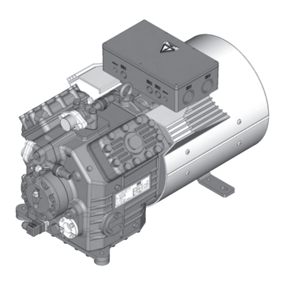
2| Product description 2.1 Brief description • Semi-hermetic four-cylinder reciprocating compressor with oil pump lubrication. • Flange-mounted drive motor on the compressor case. • Specially or deep cooling with air-cooled motor and direct suction at the cylinder. Terminal box Air guide hood Transport eyelet with fan Suction shut- off valve Cylinder Valve plate cover Discharge shut-off valve Name plate Oil pump Drive section Oil sight glass Fig. 1 Dimension and connection values can be found in Chapter 9... -
Page 7: Type Key
2| Product description 2.2 Name plate (example) GEA Bock GmbH 72636 Frickenhausen, Germany HAX4/650-4 56,6 AS35830-006 26.0 A 67,9 107 A 140 A SE 55 Fig. 2 Type designation Voltage, circuit, frequency 50 Hz Machine number Nominal rotation speed maximum operating current Displacement Starting current (rotor blocked) Voltage, circuit, frequency 60 Hz Y: Part winding 1 10 Nominal rotation speed... -
Page 8: Areas Of Application
3| Areas of application 3.1 Refrigerants • HFKW / HFC: R404A/R507 • (H)FCKW / (H)CFC: 3.2 Oil charge The compressors are filled at the factory with the following oil type: - for R404A/R507 FUCHS Reniso Triton SE 55 - for R22 FUCHS Reniso SP 46 Compressors with ester oil charge (FUCHS Reniso Triton SE 55) are marked with an X in the type designation (e.g. HAX4/650-4). INFO! For refilling, we recommend the above oil types. Alternatives: see lubricants table, Chapter 7.5. 3.3 Limits of application ATTENTION! Compressor operation is possible within the operating limits shown in the diagrams. Please note the significance of the shaded areas. - Page 9 3| Areas of application R404A R507 Fig. 3 Fig. 4 Unlimited Evaporation temperature (°C) application range Condensing temperature (°C) Reduced suction gas Suction gas superheat (K) temperature Suction gas temperature (°C) Maximum admissible operating pressure (g) High pressure side (HD): 28 bar Design for other areas on request...
-
Page 10: Compressor Assembly
4| Compressor assembly INFO! New compressors are factory-filled with inert gas (3 bar nitrogen). Leave this service charge in the compressor for as long as possible and prevent the ingress of air. Check the compressor for transport damage before starting any work. 4.1 Setting up Use transport eyelet. Do not lift manually! Use lifting gear! Fig. 5 Provide adequate clearance for maintenance work. -
Page 11: Pipes
4| Compressor assembly 4.3 Pipes Pipes and system components must be clean and dry inside and free of scale, swarf and layers of rust and phosphate. Only use air-tight parts. Lay pipes correctly. Suitable vibration compensators must be provided to prevent pipes being cracked and broken by severe vibrations. Ensure a proper oil return. Keep pressure losses to an absolute minimum. 4.4 Laying suction and pressure lines INFO! Proper layout of the suction and pressure lines directlyafter the compressor is integral to the smooth running and vibration behaviour of the system. -
Page 12: Operating The Shut-Off Valves
4| Compressor assembly 4.5 Operating the shut-off valves Before opening or closing the shut-off valve, release the valve spindle seal by approx. ¼ of a turn counter-clockwise. After activating the shut-off valve, re-tighten the adjustable valve spindle seal clockwise. Release Tighten Valve spindle seal Fig. 11 Fig. 12 4.6 Operating mode of the lockable service connections Connection cannot be Service connec- shut off tion closed Pipe connection Connection Spindle blocked Fig. 13 Opening the shut-off valve: Compressor Spindle: turn to the left (counter-clockwise) as far as it will go. —> Shut-off valve completely opened / service connection closed. The connection which cannot be shut off is intended for safety devices. Connection cannot be Service connec- shut off tion opened Pipe connection Connection... -
Page 13: Information For Contactor And Motor Contactor Selection
5| Electrical connection Electrical connection DANGER! H igh voltage! Risk of electric shock! Only carry out work when the electrical system is disconnected from the power supply! INFO! C onnect the compressor motor in accordance with the circuit diagram (see inside of terminal box). U se suitable cable entry point of the correct protection type (see name plate) for routing cables into the terminal box. I nsert the strain reliefs and prevent chafe marks on the cables. - Page 14 5.3 Basic circuit diagram for part winding start with standard motor 0 1 2 3 4 F1.2 F1.1 I=33% I=66% F1.1 F1.2 XSS Y/YY X1 L1 L1 N N 43 43 11 MP10 X2 1 Compressor terminal box AnschluastenVerdichter Fig. 15 R1 Cold conductor (PTC sensor) motor winding R2 Thermal protection thermostat (PTC sensor) Datum...
- Page 15 5 6 7 8 9 L1.1 L2.1 L3.1 L1.2 P> P< M1.1 Pl Q1 Main switch M1 Compressor motor PWMP10 M1.1 Fan motor BCKCMPRESSRS K1 Mains contactor (part winding 1) K2 Mains contactor (part winding 2) K1T Delay relay max. 1s S1 Control voltage switch E1 Oil sump heater...
- Page 16 5| Electrical connection The motor is wired for direct start (YY) at the factory. For part winding start Y / YY, the bridges must be removed and the motor feed line connected according to the circuit diagram: 400 V Direktstart YY Teilwicklungsstart Y/YY Direct start YY Part winding start Y/YY ATTENTION! F ailure to do this results in opposed rotary fields and results in damage to the motor. After the motor starts up via partial winding 1, partial winding 2 must be switched on after a maximum delay of one second .
-
Page 17: Special Motor: Design For Direct Or Star-Delta Start
5| Electrical connection 5.4 Sondermotor: Ausführung für Direkt- oder Stern-Dreieck-Anlauf 5.4 Sondermotor: Ausführung für Direkt- oder Stern-Dreieck-Anlauf 5.4 Sondermotor: Ausführung für Direkt- oder Stern-Dreieck-Anlauf 5.4 Special motor: design for direct or star-delta start Für den Stern-Dreieck-Anlauf ist eine mechanische Anlaufentlastung mit Bypass-Magnetventil Für den Stern-Dreieck-Anlauf ist eine mechanische Anlaufentlastung mit Bypass-Magnetventil Für den Stern-Dreieck-Anlauf ist eine mechanische Anlaufentlastung mit Bypass-Magnetventil (Zubehör) erforderlich. - Page 18 5.5 Circuit diagram for direct start 230 V ∆ / 400 V Y 0 1 2 3 4 F1.1 F1.1 F1.2 F1.2 XSS Net400V50 X1 L1 L1 N N 43 43 11 X2 1 2 MP10 Compressor terminal box AnschluastenVerdichter Fig. 16 R1 Cold conductor (PTC sensor) motor winding R2 Thermal protection thermostat (PTC sensor)
- Page 19 5 6 7 8 9 L1.1 L2.1 L3.1 L1.2 P> P< M1.1 Pl M1 Compressor motor M1.1 Fan motor K1 Mains contactor Δ-contactor K2 K3 Y-contactor K4T Delay relay S/D changeover MP10 BCKCMPRESSRS K5T Delay relay, start unloader S1 Control voltage switch AL Start unloader E1 Oil sump heater...
-
Page 20: Electronic Trigger Unit Mp
5| Electrical connection 5.6 Electronic trigger unit MP 10 The compressor motor is fitted with cold conductor temperature sensors (PTC) connected to the electronic trigger unit MP 10 in the terminal box. Readiness to operate is signalled by the H3 LED (green) after the power supply is applied. In the case of excess temperature in the motor winding, the unit switches off the compressor and the H1 LED lights red. The hot gas side of the compressor can also be protected against overtemperature using a thermal protection thermostat (accessory). The H2 LED (red) is provided for the protection function. The unit trips when an overload or inadmissible operating conditions occur. Find and remedy the cause. -
Page 21: Functional Test Of The Trigger Unit Mp
5| Electrical connection 5.8 Function test of the trigger unit MP 10 Before start-up, troubleshooting or making changes to the control power circuit, check the functionality of the trigger unit: LED H1 LED H2 LED H3 Procedure green • Interrupt power supply (L1 or S1) • Release the motor temperature sensor connection (1 or 2) • Release the hot gas temperature sensor (if installed) (3 or 4) • Restore the power supply (L1 or S1) •... -
Page 22: Oil Sump Heater
5| Electrical connection 5.9 Oil sump heater During compressor standstill and depending on the pressure and ambient temperature, r efrigerant diffuses into the compressor's lubricating oil. This reduces the oil's lubricating ability. When the c ompressor is started, the refrigerant contained in the oil evaporates due to the decline in pressure. This can result in oil foaming and oil exodus which can result in oil hammer in certain circumstances. In order to prevent damage to the compressor, the compressor is equipped with an oil sump heater as standard. The oil sump heater must always be connected and operated. Operation mode: The oil sump heater operates when the compressor is shut down. The oil sump heater is switched off when the compressor starts. Connection: Connect the oil sump heater via an auxiliary contact (or parallel-wired auxiliary Anschlussschema für Ölsumpfheizung c ontactor) of the compressor contactor to a separate current path. Connection diagramm for oil sump heater Electrical data: 230 V - 1 - 50/60 Hz, 80 W. Plan de raccordement pour résistance de carter d‘huile Fig. 18 ATTENTION! Connection to the current path of the safety control chain is not permitted... -
Page 23: Commissioning
6| Commissioning 6.1 Preparations for start-up INFO! In order to protect the compressor against inadmissible operating conditions, high-pressure and low-pressure pressostats controls are mandatory on the installation side. The compressor has undergone trials in the factory and all functions have been tested. There are therefore no special running-in instructions. Check the compressor for transport damage! 6.2 Pressure strength test WARNING! The compressor must never be pressurised using oxygen or other technical gases! The maximum permissible overpressure of the compressor must not be exceeded at any time during the testing process (see name plate... - Page 24 6| Commissioning 6.5 Refrigerant filling CAUTION! Wear personal protective clothing such as goggles and protective gloves! Make sure that the suction and pressure line shut-off valves are open. With the compressor switched off, add the liquid refrigerant directly to the condenser or receiver, breaking the vacuum. If the refrigerant needs topping up after starting the compressor, it can be topped up in vapour form on the suction side, or, taking suitable precautions, also in liquid form at the inlet to the evaporator. INFO! Avoid overfilling the system with refrigerant! I n order to prevent shifts in concentration, zeotropic refrigerant blends (e.g. R407C) must always only be added to the refrigerating system in liquid form.
-
Page 25: Connection Of Oil Level Regulator
6| Commissioning 6.8 Connection of oil level regulator Oil level regulation systems have proven themselves with parallel circuits of several compressors. The connection "0" is provided for installing an oil level regulator (see dimensions drawing). All common oil level regulators from AC&R, ESK and Carly as well as the OM3 TraxOil oil level regulation system from Alco can be connected directly without adapters (see Fig. 19). A sight glass on the oil level regulator is not required. Anschluss Ölspiegelregulator Bei Verbundschaltungen von mehreren Verdichtern haben sich Ölstandsregulierungssysteme bewährt. Für die Montage eines Ölspie- M6 x 10 gelregulators ist der Anschluss „O“ vorgesehen (siehe Maßzeichnung). je 3 mal 3 times each Alle gängigen Ölspiegelregulatoren von AC&R, ESK sowie das elek-... -
Page 26: Accessories
7| Maintenance 7.3 Recommended spare parts 385-4 555-4 HA4 / ... 310-4 465-4 650-4 Ref. No. Ref. No. Ref. No. Designation Set of gaskets 08931 Valve plate kit 08888 08690 08889 Oil pump kit 08384 Oil sump heater kit 08425 230 V ~ BS AL/LR 220-240 V 08527 Only use genuine Bock spare parts! 7.4 Accessories Available accessories can be found on the Internet at www.bock.de. 7.5 Extract from the lubricants table The oil type filled as standard in the factory is marked on the name plate. -
Page 27: Technical Data
8| Technical data 380-420 V Y/YY - 3 - 50 Hz PW 440-480 V Y/YY - 3 - 60 Hz PW PW = Part Winding Winding ratio: 66% / 33%... -
Page 28: Dimensions And Connections
9| Dimensions and connections Änderungen vorbehalten Maße in mm Massenschwerpunkt ca.400 Subject to change without notice Dimensions in mm Centre of gravity Sous réserve de toutes modifications Cotes en mm Centre de gravité Centre of gravity DV L A A1 N B SV Ansich View X Vue X... - Page 29 9| Dimensions and connections Suction line see technical data, Chapter 8 Discharge line Connection suction side, not lockable 8 “ NPTF Connection suction side, lockable 16 “ UNF Connection discharge side, not lockable 8 “ NPTF Connection discharge side, lockable 16 “ UNF Connectoin oil pressure switch OIL 16 “ UNF Connection oil pressure switch LP 16 “ UNF Connection oil return from oil separator 4 “ NPTF Connection oil pressure gauge 16 “ UNF Oil drain M22 x 1,5 Oil charge plug M22 x 1,5...
-
Page 30: Declaration Of Conformity And Installation
10| Declaration of conformity and installation DECLARATION OF CONFORMITY CE 09 for using the compressors within the European Union (in accordance with Low Voltage Directive 2006/95/EC) We hereby declare that the following refrigerating compressors Product designation: HA4 comply with the Low Voltage Directive 2006/95/EC. Applied harmonised standard: EN 60034-1, EN 60204-1 DECLARATION OF INSTALLATION for using the compressors within the European Union (in accordance with Machinery Directive 2006/42/EC) The manufacturer: GEA Bock GmbH, Benzstraße 7 72636 Frickenhausen, Tel.: 07022/9454-0 hereby declares that the refrigerating compressor HA4 complies with the basic requirements of Appendix II 1B of the Machinery Directive 2006/42/EC. The following harmonised standards have been applied: EN ISO 12100-1 EN ISO 12100-2 EN 12693 EN 349 A partly completed machine may only be put into operation when it has been established that the machine, into which the partly completed machine is to be installed, conforms to the r egulations of the Machinery Directive (2006/42/EC). -
Page 31: Service
11| Service Dear customer, Bock compressors are top-quality, reliable and service-friendly quality products. If you have any questions about installation, operation and accessories, please contact our technical service or specialist wholesaler and/or our representative. The Bock service team can be contacted +49 7022 9454-0 by phone: via e-mail: mail@bock.de or on the Internet at: www.bock.de In addition, for German-speaking countries we have set up a toll-free Bock hotline 00 800 / 800 000 88 from Monday to Saturday between 8 am and 9 pm. Any suggestions you may have regarding the on-going development of our compressor, equipment Sehr geehrter Kunde, and parts programme are welcome at any time. Bock-Verdichter sind hochwertige, zuverlässige und servicefreundliche Qualitätsprodukte. U Yours faithfully Vorteile in vollem Umfange und über den gesamten Einsatzzeitraum Ihrer Kälteanlage nutze können, beachten Sie unbedingt die folgenden Bedienungs- und Wartungshinweise. - Page 32 Corporate Design Manual _ In touch with our corporate design GEA Refrigeration Technologies www.gearefrigeration.com, www.bock.de www.gearefrigeration.com...
Need help?
Do you have a question about the In Touch HA4/310-4 and is the answer not in the manual?
Questions and answers