Advertisement
Quick Links
Quick Start Guide
Opto-electronic Network Analyzer
Systems
VNA, O/E Calibration Module, and E/O Converter:
ME7848A/E-0210, 110 GHz 1550 nm system
ME7848A/E-0211, 110 GHz 1310 nm system
ME7848A-0240, 40 GHz 850 nm system
ME7848A-0270, 70 GHz 1550 nm system
ME7848A-0271, 70 GHz 1310 nm system
ME7848A-0272, 70 GHz 1310/1550 nm system
VNA and O/E Calibration Module only
ME7848A/E-0110 110 GHz, 1550 nm system
ME7848A/E-0111 110 GHz, 1310 nm system
ME7848A/E-0112 110 GHz, 1310/1550 nm system
ME7848A-0140 40 GHz, 850 nm system
ME7848A-0170 70 GHz, 1550 nm system
ME7848A-0171 70 GHz, 1310 nm system
ME7848A-0172 70 GHz, 1310/1550 nm system
Anritsu Company
Part Number: 10410-00777
490 Jarvis Drive
Revision: C
Morgan Hill, CA 95037-2809
Published: October 2023
USA
Copyright 2023 Anritsu Company. All rights reserved.
http://www.anritsu.com
Advertisement

Related Manuals for Anritsu Company VectorStar ME7848A/E-0210


Summary of Contents for Anritsu Company VectorStar ME7848A/E-0210
- Page 1 ME7848A-0170 70 GHz, 1550 nm system ME7848A-0171 70 GHz, 1310 nm system ME7848A-0172 70 GHz, 1310/1550 nm system Anritsu Company Part Number: 10410-00777 490 Jarvis Drive Revision: C Morgan Hill, CA 95037-2809 Published: October 2023 Copyright 2023 Anritsu Company. All rights reserved. http://www.anritsu.com...
- Page 2 NOTICE Anritsu Company has prepared this manual for use by Anritsu Company personnel and customers as a guide for the proper installation, operation and maintenance of Anritsu Company equipment and computer programs. The drawings, specifications, and information contained herein are the property of Anritsu Company, and any unauthorized use or disclosure of these drawings, specifications, and information is prohibited;...
- Page 3 1. Minimum Configurations Opto-electronic Network Analyzer System The ME7848A/E opto-electronic network analyzer (ONA) system comprises a VNA, a calibration O/E module, and a laser/modulator converter assembly. Together, they allow calibrated RF response measurements of E/O, O/E, and certain O/O devices. This document describes the system components, basic connection and operation information, and some simple test steps to assure that the system is operating normally.
- Page 4 1. Minimum Configurations Table 1. ME7848A/E ONA System Configuration Options (2 of 3) ME7838AX Broadband VectorStar VNA MN4765B-0111 110 GHz 1310 Calibration Module (with characterization files) MN4775A-0111 110 GHz 1310 nm E/O Converter ME7848A-0211 2000-2119-R Accessory Kit which includes: 110 GHz 1310 nm System •...
- Page 5 1. Minimum Configurations Table 1. ME7848A/E ONA System Configuration Options (3 of 3) MS4747B 70 GHz VectorStar VNA with Option 051, 061, or 062 MN4765B-0071 70 GHz 1310 Calibration Module (with characterization files) MN4775A-0071 70 GHz 1310 nm E/O Converter 2000-1958-R Accessory Kit which includes: ME7848A-0271 •...
-
Page 6: System Connections
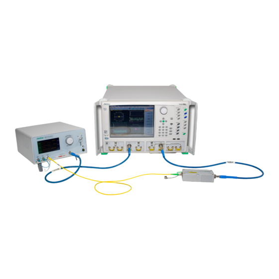
2. System Connections System Connections The basic system connections are illustrated in Figure 1 (for the 40 and 70 GHz system configurations; a similar setup for the 110 GHz systems is used, except the VNA is a broadband configuration). Port 1 of the VNA is connected to the E/O modulator (the MN4775A in the -02xx systems) and Port 2 of the VNA is connected to the MN4765B O/E calibration module. - Page 7 2. System Connections The user's DUT (an E/O, O/E or O/O device) would substitute into one of the positions shown in the figure and the remaining system components calibrated or de-embedded out to reveal the DUT response. The MN4765B can also be connected to VNA Port 1 (and E/O converter to VNA Port 2) if desired. Figure 2.
-
Page 8: System Check
3. System Check Consult the ME7848A/E Technical Data Sheet – 11410-01145 for more information on the amount of dynamic range/noise floor improvement possible with the ‘reversed’ vs. the ‘normal’ coupler arrangement, but it is generally on the order of 10 dB at low frequencies, decreasing to 0 dB slightly above 40 GHz. Figure 4. - Page 9 3. System Check 5. For the ME7848A/E-0210: a. Configure the MN4775A-0110 E/O Converter. i. Turn the laser on. A. Adjust the wavelength to 1550 nm. ii. Set the modulator bias to quadrature. A. Initiate a bias calibration. iii.Set the VOA (variable optical amplifier) to constant power output and +3 dBm. 6.
- Page 10 3. System Check b. Configure the MN4775A-0072 E/O converter for 1310 nm operation: i. Turn the laser on. A. Set the wavelength to 1310 nm. ii. Set the modulator bias to quadrature and dither. A. Initiate a bias calibration iii.Set the VOA (variable optical amplifier) to constant power output and +2 dBm. iv.
-
Page 11: Functional Test
3. System Check Functional Test 1. Measurement setup a. Set the VNA to sweep from 70 kHz to the 40/70/110 GHz (depending on the system), 201 points, 100 Hz IFBW, +5 dBm for -0240 systems and -10 dBm for the -021x/-027x systems. b. - Page 12 4. Making Opto-electronic Component Measurements Making Opto-electronic Component Measurements The typical measurement scenario with the ME7848A/E opto-electronic network analyzer system is to analyze the conversion behavior of E/O or O/E devices or to study the RF envelope behavior for signals passing through O/O components.
- Page 13 4. Making Opto-electronic Component Measurements Figure 4. E/O Measurement Dialog O/E Measurements In this case, the E/O device must be de-embedded. Sometimes, the .s2p file of that device is available but, if not, a two-step process is used. The MN4765B is connected to the E/O device (the MN4775A usually) and the VNA tools are used to generate the .s2p file for the MN4775A by de-embedding the MN4765B.
- Page 14 4. Making Opto-electronic Component Measurements O/O Measurements These measurements require de-embedding of both O/E and E/O devices and the pattern should be obvious from the previous subsections. The O/O measurements described here are slightly different from those one might conduct with optical power meters or optical spectrum analyzers in that the system monitors what happens to the RF envelope.
- Page 15 4. Making Opto-electronic Component Measurements ME7848A/E QSG PN: 10410-00777 Rev. C QSG-15...
- Page 17 Anritsu Company 490 Jarvis Drive Anritsu utilizes recycled paper and environmentally conscious inks and toner. Morgan Hill, CA 95037-2809 http://www.anritsu.com...
Need help?
Do you have a question about the VectorStar ME7848A/E-0210 and is the answer not in the manual?
Questions and answers