
Related Manuals for Anritsu Company Site Master S312D


Summary of Contents for Anritsu Company Site Master S312D
- Page 1 Maintenance Manual Site Master Model S312D Cable, Antenna, and Spectrum Analyzer Anritsu Company P/N: 10580-00195 490 Jarvis Drive Revision: B Morgan Hill, CA 95037-2809 Printed: July 2009 Copyright 2009 Anritsu Company...
- Page 3 Safety Symbols To prevent the risk of personal injury or loss related to equipment malfunction, Anritsu Company uses the following symbols to indicate safety-related information. For your own safety, please read the information carefully before operating the equipment. Symbols Used in Manuals...
- Page 4 For Safety Warning Always refer to the operation manual when working near locations at which the alert mark, shown on the left, is attached. If the operation, etc., is performed without heeding the advice in the operation manual, there is a risk of personal injury.
-
Page 5: Table Of Contents
Table of Contents Chapter 1—General Information Introduction ..............1-1 Description . - Page 6 Table of Contents (Continued) Removal and Replacement Procedures ......... . 3-4 Important Information Regarding Service of Anritsu Equipment .
-
Page 7: Chapter 1-General Information
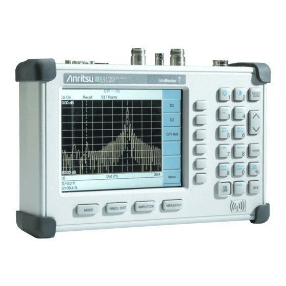
Chapter 1 — General Information Introduction This manual provides maintenance instructions for the Site Master Model S312D Cable, Antenna and Spectrum Analyzer. It describes the product and provides performance verification procedures, parts replacement procedures, and a replaceable parts list. Description The Site Master is a handheld SWR/RL (standing wave ratio/return loss), Distance-To-Fault, spectrum analysis, and power meter (optional) measurement instrument. -
Page 8: Recommended Test Equipment
1-3 Recommended Test Equipment General Information Recommended Test Equipment Table 1-1. Required Equipment for Performance Verification Recommended Instrument Critical Specification Manufacturer/Model Synthesized Signal Generator Frequency: 0.1 Hz to 20 GHz Anritsu Model MG3692A or B with Option 2A and Option 4 Power Meter Power Range: –70 dBm to +20 dBm Anritsu Dual Channel Power Meter... -
Page 9: Replaceable Parts
General Information 1-4 Replaceable Parts Replaceable Parts Table 1-2. List of Replaceable Assemblies Part Number Description ND67965 S312D Main/SPA Assembly (without Option 10A, without Option 31) ND67967 S312D Main/SPA Assembly (with Option 31, without Option 10A) ND67969 S312D Main/SPA Assembly (with Option 10A, without Option 31) ND67971 S312D Main/SPA Assembly (with both Option 31 and Option 10A) ND66432 Option 5 PCB 3-633-26 Coin Battery for RTC... - Page 10 1-4 Replaceable Parts General Information PN: 10580-00195 Revision B S312D MM...
-
Page 11: Chapter 2-Performance Verification
Performance Verification The following sections contain tests that can be used to verify the performance of the Site Master S312D. Before performing any of the tests in these sections, ensure that the S312D has had a minimum of 30 minutes warm up and that the test equipment has been warmed up to the specifications of its manufacturer. -
Page 12: Vna Frequency Accuracy
Site Master is not required for this test. Table 1-1): Required Equipment (refer to • Spectrum Analyzer, Anritsu Model MS2665C • Frequency Reference Symmetricom Rubisource T&M • Site Master S312D MS2665C Spectrum Analyzer 9kHz–21.2GHz Freq/Ampl Marker Entry... - Page 13 Performance Verification 2-2 VNA Frequency Accuracy b. Press the Frequency key. c. Set the Center Frequency to 1 GHz. d. Press the Span key. e. Set the frequency span to 750 kHz. f. Press the RBW key. g. Set the RBW to 10 kHz. h.
-
Page 14: Vna Return Loss Verification
The following test can be used to verify the accuracy of return loss measurements. Measurement calibration of the Site Master is required for this test. Table 1-1): Required Equipment (refer to • Site Master S312D • Open/Short, Anritsu Model 22N50 • 50 ohm termination, Anritsu Model 28N50-2 22N50 28N50-2... -
Page 15: Instacal Module Verification
Module (part number ICN50) is an optional accessory for the S312D. Table 1-1): Required Equipment (refer to • Site Master S312D • InstaCal Module • Offset Termination, 6 dB, Anritsu Model SC5237 • Offset Termination, 20 dB, Anritsu Model SC5270... - Page 16 2-4 InstaCal Module Verification Performance Verification If this particular InstaCal Module has been used previously to calibrate this Site Master, then the Site Master senses the familiar InstaCal Module and automatically calibrates the instrument by using the OSL procedure. If the Site Master senses that the characterization data for the InstaCal Module that is connected to this Site Master is different than the characterization data that is currently stored, then it displays soft key options to keep or to replace the InstaCal characterization data.
-
Page 17: Spectrum Analyzer Frequency Accuracy
The following test can be used to verify the CW frequency accuracy of the Site Master Spectrum Analyzer. Table 1-1): Required Equipment (refer to • Anritsu Model MG3692x Synthesized Signal Generator • Frequency Reference Symmetricom Rubisource T&M • Site Master S312D to rear panel MG369XA Source connector 10 MHz Reference S332D... - Page 18 2-5 Spectrum Analyzer Frequency Accuracy Performance Verification b. Press the RBW Manual soft key and use the Up/Down arrow key to select 100 Hz. Press ENTER to set the resolution bandwidth to 100 Hz. c. Press the VBW Manual soft key and use the Up/Down arrow key to select 30 Hz. Press ENTER to set the video bandwidth to 30 Hz.
-
Page 19: Spectrum Analyzer Phase Noise Verification
Required Equipment (refer to • Anritsu Model MG3692x Synthesized Signal Generator • Frequency Reference Symmetricom Rubisource T&M • Site Master S312D Procedure: 1. Connect the output of the Synthesized Signal Generator to the Site Master RF Input. (Refer to Figure 2-4.) -
Page 20: Input Related Spurious Response Verification
1-1): Required Equipment (refer to • Anritsu Model MG3692x Synthesized Signal Generator • Frequency Reference Symmetricom Rubisource T&M • Lowpass Filter, Anritsu Part Number 1030-96 (RLC Electronics) • Site Master S312D Low Pass Filter to rear panel MG369XA Source connector... - Page 21 Performance Verification 2-7 Input Related Spurious Response Verification 8. Press the Scale soft key and enter 7 then press ENTER. 9. Press the Atten/Preamp soft key and then the Manual soft key. 10. Enter 0 and press ENTER to set the attenuation to 0 dB. 11.
-
Page 22: Spectrum Analyzer Resolution Bandwidth Accuracy Verification
Required Equipment (refer to • Anritsu Model MG3692x Synthesized Signal Generator • Frequency Reference Symmetricom Rubisource T&M • Site Master S312D Procedure: 1. Connect the 10 MHz reference source to the Synthesized Signal Generator and the Ext Freq Ref input of the Site Master. -
Page 23: 100 Khz Rbw Test
Performance Verification 2-8 Spectrum Analyzer Resolution Bandwidth Accuracy Verification 100 kHz RBW Test 1. Press the FREQ/DIST key. 2. Press the Span soft key, enter 150 and press the kHz soft key to set the span to 150 kHz. 3. Press the MEAS/DISP key and the Bandwidth soft key. 4. -
Page 24: 300 Hz Rbw Test
2-8 Spectrum Analyzer Resolution Bandwidth Accuracy Verification Performance Verification 4. Press the RBW Manual soft key and use the Up/Down arrow key to select 1 kHz. Press ENTER to set the resolution bandwidth to 1 kHz and press BACK. 5. Press the Measure soft key then the MARKER key. 6. -
Page 25: Spectrum Analyzer Level Accuracy Verification
• Fixed Attenuator, Aeroflex/Weinschel Model 44-10 • Fixed Attenuator, Aeroflex/Weinschel Model 44-30 • RF Coaxial Cable, Anritsu Model 15NN50-1.5C • Adapter, Anritsu Model 34RKNF50 • Adapter, Anritsu Model 34NN50A • Site Master S312D ML2438A Power Meter Sensor B 34RKNF50 Adapter... -
Page 26: Level Accuracy With Frequency Test
2-9 Spectrum Analyzer Level Accuracy Verification Performance Verification Level Accuracy with Frequency Test Procedure: 1. Turn on the power meter and the Synthesized Signal Generator as shown in Figure 2-6. 2. On the power meter, press the Channel key, the Setup soft key, and then the CHANNEL soft key to display the Channel 2 setup menu. - Page 27 Performance Verification 2-9 Spectrum Analyzer Level Accuracy Verification Sensor A ML2438A Power Meter Sensor B 34RKNF50 Adapter 1870A Power Splitter 10 dB Attenuator to rear panel MG369XA Source 15NNF50-1.5B connector 34NN50A Adapter S332D Site Master SiteMaster ESCAPE 10 MHz Reference CLEAR START AUTO...
- Page 28 2-9 Spectrum Analyzer Level Accuracy Verification Performance Verification 29. On the Power Meter, press the Sensor key and then the CalFactor soft key. Press the FREQ soft key and enter 30 MHz for the Input Signal Frequency. This sets the power meter to the proper power sensor calibration factor.
-
Page 29: Level Accuracy With Power Test
Performance Verification 2-9 Spectrum Analyzer Level Accuracy Verification Level Accuracy with Power Test Procedure: 1. Use the recorded values of C and E for 50 MHz in Table A-7, “Spectrum Analyzer Level Accuracy Verification Output Power Levels” on page A-5 to calculate the desired Sensor B Reading for Test Power Level >... - Page 30 2-9 Spectrum Analyzer Level Accuracy Verification Performance Verification 24. Disconnect Sensor A from the Synthesized Signal Generator output. 25. Connect the power splitter to the Synthesized Signal Generator output and connect Sensor B to one of the power splitter output connections. Install the 30 dB fixed attenuator to the other power splitter output connection, and connect Sensor A to the attenuator as shown in Figure 2-8.
- Page 31 Performance Verification 2-9 Spectrum Analyzer Level Accuracy Verification 32. Using the power splitter, coaxial cable, adapters, and 30 dB fixed attenuator, connect the Site Master to the signal source and the power sensor as shown in Figure 2-9. Sensor A ML2438A Power Meter Sensor B 34RKNF50...
-
Page 32: 2-10 Spectrum Analyzer Residual Spurious Response Verification
The following test can be used to verify the residual spurious response of the Site Master Spectrum Analyzer. This test is performed using the positive peak detection mode. Table 1-1): Required Equipment (refer to • 50 ohm termination, Anritsu Model 28N50-2 • Site Master S312D 28N50-2 S332D Site Master SiteMaster ESCAPE... - Page 33 Performance Verification 2-10 Spectrum Analyzer Residual Spurious Response Verification 16. Record the M1 amplitude reading in Table A-13, “Spectrum Analyzer Residual Spurious Response Verification” on page A-8 and verify that it is ≤ –80 dBm. If a spur with an amplitude larger than –80 dBm occurs, then wait another full sweep and observe Note whether the spur occurs at the same point on the second sweep.
-
Page 34: Spectrum Analyzer Displayed Average Noise Level (Danl)
RMS detection mode, with preamp on. Table 1-1): Required Equipment (refer to • 50 ohm termination, Anritsu Model 28N50-2 • Site Master S312D Procedure: 1. Connect the 28N50-2 50 Ohm termination to the S312D Spectrum Analyzer RF In. (Refer to Figure 2-10.) 2. -
Page 35: Power Monitor Verification (Option 5)
1-1): Required Equipment (refer to • Anritsu Model MG3692x Synthesized Signal Generator • Power Meter, Anritsu Model ML2438A • Site Master S312D • Power Splitter, Aeroflex/Weinschel Model 1870A • Power Sensor, Anritsu Model MA2442D • RF Detector, Anritsu Model 560-7N50B •... -
Page 36: Bias Tee Verification (Option 10A)
If the Bias Tee (Option 10A) is installed in the S312D, then the following test can be used to verify the performance of the bias termination. Table 1-1): Required Equipment (refer to • Site Master S312D • Low Current Load Fixture, 105 ohm, Anritsu Part T3377 • Low Current Load Fixture, 40 ohm, Anritsu Part T2904 T2904 T3377... -
Page 37: Fault Test
The test in this section can be used to verify the Dynamic Range of a Site Master equipped with Option 21. Table 1-1): Required Equipment (refer to • Site Master S312D • RF Coaxial Cable, Anritsu Model 15NN50-1.5C • 50 ohm termination, Anritsu Model 28N50-2 Procedure: 1. -
Page 38: Power Meter Verification (Option 29)
1-1): Required Equipment (refer to • Anritsu Model MG3692x Synthesized Signal Generator • Power Meter, Anritsu Model ML2438A • Site Master S312D • Power Splitter, Aeroflex/Weinschel Model 1870A • Power Sensor, Anritsu Model MA2442D • Fixed Attenuator, Aeroflex/Weinschel Model 44-10 •... - Page 39 Performance Verification 2-15 Power Meter Verification (Option 29) Procedure: 1. Turn on the power meter and signal source. 2. On the power meter, press the Channel key, the Setup soft key and then the CHANNEL soft key to display Channel 2 setup menu. Press the INPUT key twice to set the input configuration to B. Press the Sensor key to display both Sensor A and Sensor B Readings.
- Page 40 2-15 Power Meter Verification (Option 29) Performance Verification Sensor A ML2438A Power Meter Sensor B 34RKNF50 Adapter 1870A Power Splitter 10 dB Attenuator MG369XA Source 15NNF50-1.5B 34NN50A Adapter S332D Site Master SiteMaster ESCAPE CLEAR START AUTO SCALE SAVE RECALL SETUP SETUP LIMIT MARKER...
-
Page 41: Chapter 3-Removal And Replacement
Chapter 3 — Removal and Replacement Battery Pack Removal and Replacement This procedure provides instructions for removing and replacing the Site Master battery pack.Table 2-1 Chapter 1, “General Information” provides a list of replaceable assemblies. Many of the procedures in this section are generic, and apply to many similar instruments. Photos Note and illustrations that are used in this document are representative and may show instruments other than the Site Master. -
Page 42: Battery Information
3-2 Battery Information Removal and Replacement 5. Replacement of the battery is the reverse of removal. Note the orientation of the battery contacts, and be sure to insert the new battery with the contacts facing the rear of the instrument (Figure 3-2). -
Page 43: Battery Testing Procedure
Removal and Replacement 3-2 Battery Information Battery Testing Procedure 1. With the Site Master Off and the battery installed, connect the Universal AC Adapter to the 12.5–15VDC (1350 mA) connector. The External Power LED and the Battery Charging LED will light. If the Battery Charging LED does not light, the battery may be too low to immediately begin full charging. -
Page 44: Removal And Replacement Procedures
3-3 Removal and Replacement Procedures Removal and Replacement Removal and Replacement Procedures Table 1-2, “List of Replaceable Assemblies” on page 1-3 provides a list of replaceable assemblies. Important Information Regarding Service of Anritsu Equipment Only qualified service personnel should attempt to perform repairs on this instrument. During the warranty period, opening of the case by non-Anritsu Service personnel will void the warranty. -
Page 45: Opening The Case
Removal and Replacement 3-4 Opening the Case Opening the Case ESD Requirements: The model S312D contains components that can be easily damaged by electrostatic discharge (ESD). An ESD safe work area and proper ESD handling procedures that conform to ANSI/ESD S20.20-1999 or ANSI/ESD S20.20-2007 are mandatory to avoid ESD Caution damage when handling subassemblies or components that are found in the S312D instrument. -
Page 46: Removal Of The Main Pcb, Option 5 Pcb, Spectrum Analyzer Assembly
3-6 Removal of the Main PCB, Option 5 PCB, Spectrum Analyzer Assembly Removal and Replacement Removal of the Main PCB, Option 5 PCB, Spectrum Analyzer Assembly 1. Remove the 2 screws at the bottom of the main PCB, one screw in the center, and the 5-wire battery cable. -
Page 47: Rtc Battery Information
Removal and Replacement 3-7 RTC Battery Information Figure 3-5. S312D Spectrum Analyzer PCB RTC Battery Information The date and time are saved using a +3 V coin-style battery that is mounted on the main PCB. (Refer to Figure 3-6 for the location). This battery has a finite life span. When sufficiently discharged, the message RTC Invalid appears during the boot-up self-test. - Page 48 3-7 RTC Battery Information Removal and Replacement PN: 10580-00195 Revision B S312D MM...
-
Page 49: Appendix A-Test Records
Appendix A — Test Records This appendix provides test records that can be used to record the performance of the S312D. Please make a copy of the following Test Record pages and document the measured values each time a Performance Verification is performed. - Page 50 Test Records S312D Firmware Revision: ________________ Operator: ________________ Date: ______________ Serial Number: ________________ Options: ___________________________________________________ VNA Frequency Accuracy Table A-1. VNA Frequency Accuracy Measured Value Specifications 1000 MHz ± 75 kHz 1000 MHz ± 75 kHz Use the first row for the VNA Frequency Accuracy test. If the test fails, then use the second row for the repeated test.
-
Page 51: Spectrum Analyzer Frequency Accuracy
Test Records S312D Firmware Revision: ________________ Operator: ________________ Date: ______________ Serial Number: ________________ Options: ___________________________________________________ Spectrum Analyzer Frequency Accuracy Table A-3. Spectrum Analyzer Frequency Accuracy Measured Value Specifications 1000 MHz ± 2 kHz 1000 MHz ± 2 kHz Use the first row for the VNA Frequency Accuracy test. If the test fails, then use the second row for the repeated test. - Page 52 Test Records S312D Firmware Revision: ________________ Operator: ________________ Date: ______________ Serial Number: ________________ Options: ___________________________________________________ Input Related Spurious Response Verification Table A-5. Spectrum Analyzer Input Related Spurious Response Verification M1 + 30 dB Specification ≤ –40 dBc Spectrum Analyzer Resolution Bandwidth Accuracy Verification Table A-6.
- Page 53 Test Records S312D Firmware Revision: ________________ Operator: ________________ Date: ______________ Serial Number: ________________ Options: ___________________________________________________ Spectrum Analyzer Level Accuracy Verification Table A-7. Spectrum Analyzer Level Accuracy Verification Output Power Levels Sensor A Sensor A Splitter/Attenuator Sensor B Sensor B Path Freq Reading at Reading at...
-
Page 54: Spectrum Analyzer Level Accuracy Verification (Continued
Test Records S312D Firmware Revision: ________________ Operator: ________________ Date: ______________ Serial Number: ________________ Options: ___________________________________________________ Spectrum Analyzer Level Accuracy Verification (continued) Table A-9. Spectrum Analyzer Level Accuracy with Frequency Frequency Measured Value at 0 dBm Measured Value at –39 dBm Specification 30 MHz ±... - Page 55 Test Records S312D Firmware Revision: ________________ Operator: ________________ Date: ______________ Serial Number: ________________ Options: ___________________________________________________ Spectrum Analyzer Level Accuracy Verification (continued) Table A-11. Spectrum Analyzer Level Accuracy with Power Input Power Level Reference Level Specification Measured Marker M1 Reading +3 dBm +10 dBm ±1.5 dB 0 dBm...
- Page 56 ≤ –135 dBm 10 MHz to 1.6 GHz Power Monitor Verification (Option 5) Table A-15. Power Monitor Verification (Option 5) Power Site Master S312D Power Reading Specification 0 dBm 0 dBm ± 1.0 dB –7 dBm –7.0 dBm ± 1.0 dB –12 dBm...
- Page 57 Test Records S312D Firmware Revision: ________________ Operator: ________________ Date: ______________ Serial Number: ________________ Options: ___________________________________________________ Power Meter Verification (Option 29) Table A-17. Power Meter Verification (Option 29) Output Power Level Sensor A Sensor A Splitter/Attenuator Sensor B Sensor B Path Freq Reading at Reading at...
- Page 58 Test Records A-10 PN: 10580-00195 Revision B S312D MM...
-
Page 59: Appendix B-Test Fixture Schematics
Appendix B — Test Fixture Schematics The following schematics are provided for those wishing to build their own test fixtures for the Option 10A verification test. The part numbers referenced in the schematics are Anritsu part numbers. Figure B-1. Anritsu Model T2904 High Current Test Fixture (for Option 10A) Figure B-2. - Page 60 Test Fixture Schematics PN: 10580-00195 Revision B S312D MM...
- Page 62 Printed on Recycled Paper with Vegetable Soybean Oil Ink Anritsu Company 490 Jarvis Drive Morgan Hill, CA 95037-2809 http://www.anritsu.com/...
Need help?
Do you have a question about the Site Master S312D and is the answer not in the manual?
Questions and answers