Advertisement
Quick Links
Quick Start Guide
ShockLine™ Series
Vector Network Analyzers
Verification Kits and
Performance Verification Software
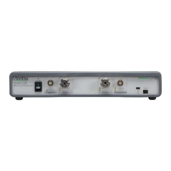
MS46122B Series VNAs
MS46322B Series VNAs
MS46522B Series VNAs
MS46524B Series VNAs
Anritsu Company
Part Number: 10410-00766
490 Jarvis Drive
Revision: B
Morgan Hill, CA 95037-2809
Published: April 2019
USA
Copyright 2019 Anritsu Company
Advertisement

Related Manuals for Anritsu Company ShockLine MS46122B Series


Summary of Contents for Anritsu Company ShockLine MS46122B Series
- Page 1 Vector Network Analyzers Verification Kits and Performance Verification Software MS46122B Series VNAs MS46322B Series VNAs MS46522B Series VNAs MS46524B Series VNAs Anritsu Company Part Number: 10410-00766 490 Jarvis Drive Revision: B Morgan Hill, CA 95037-2809 Published: April 2019 Copyright 2019 Anritsu Company...
-
Page 2: Verification Kit Components
1. Introduction to the Quick Start Guide Introduction to the Quick Start Guide This quick start guide provides a brief overview of the installation and use of ShockLine Verification Kits and the 3-2300-610 Performance Verification Software (PVS) with ShockLine™ Series VNAs. Verification Kit Components The supplied Verification Kit components are listed in the general reference figure below. - Page 3 2. Verification Kit Components Calibration/Verification Kit Components Summary of Required Hardware The table below summarizes the required support hardware for each verification kit. Only one calibration kit, automatic or manual, is required. Note also that the PC Controller and the connecting GPIB cable are required for all VNAs and all verification kits.
-
Page 4: Component Description
3. Required PC Controller Equipment Required PC Controller Equipment The following Personal Computer (PC) Controller equipment and software are required to control the ShockLine Series VNA. The PC Controller and the VNA are connected over an Ethernet network. The required Ethernet cable, test port adapters, and phase-stable through line with any required adapters are not included in the verification kit. - Page 5 4. PC Controller Cable Connections to VNA PC Controller Cable Connections to VNA MS46524B Verification Component Connection The basic connections between the PC Controller, the MS46524B VNA, and the verification components are shown below. See Figure 2 below. Note: For the MS46524B: Port-1/Port-2 are verified as a set and Port-3 and Port-4 are verified as a set.
- Page 6 4. PC Controller Cable Connections to VNA MS46322B Verification Component Connection The basic connections between the PC Controller, the MS46322B VNA, and the verification components are shown below. See Figure 4 below. 1. ShockLine Series VNA 5. Port 1 Adapter (if needed) 2.
-
Page 7: Installing The Software
5. Installing the ShockLine Performance Verification Software (PVS). Installing the ShockLine Performance Verification Software (PVS) This section describes how to install the Performance Verification Software (PVS) application and how to use the PVS user interface functions. Installing the Software The software is contained on the USB Memory Device supplied with each Verification Kit. Refer to Section 2. - Page 8 5. Installing the ShockLine Performance Verification Software (PVS). Anritsu ShockLine Verification Program Screen When the PVS Installation is complete, the Verification Software navigation page will then appear. See Figure 1. Menu Bar – File, Utilities, Help 8. Test Result– Test results Display 2.
- Page 9 5. Installing the ShockLine Performance Verification Software (PVS). Setup the VNA and Verification Performance Software communication The Performance Verification Software program must be set-up to communicate with the VNA. To locate the VNA Network Address, on the VNA select: Main Menu | System | Network Interface. Refer to Figure 8.
- Page 10 Adding Performance Verification Tools This section describes how to enter the required testing tools and components into the PVS program to perform a full performance verification. Adding the PVS Tools The following tools are required to perform a full VNA performance verification: Verification Kit •...
- Page 11 6. Adding Performance Verification Tools • A Import Verification Kit Data screen will appear. See Figure 10 Figure 10. Import Verification Kit Data Screen 5. Insert the MS46xxxB Models 3-2300-610 USB Flash Drive into a USB port on the PC. 6.
- Page 12 6. Adding Performance Verification Tools • Here you can add components to the Station Asset Utility list that are required for the Performance Verification testing, e.g. TOSLKF50A-40 and TOSLK50A-40. Figure 12. Additional Asset Information 13. Enter the Performance Verification tools adapters etc. into each field. 14.
- Page 13 7. Starting Performance Verification Testing Starting Performance Verification Testing This section describes the performance verification testing process. 1. From the main Performance Verification Menu screen, select Start Session located at the top center part of the PVS screen. See.Figure 14 1.
- Page 14 7. Starting Performance Verification Testing • Figure 15. Starting New Session 2. Select OK to start your Performance Verification testing. • An Unable to Connect Message will display when there is a discrepancy in the setup. The problem must be resolved before continuing with testing. 3.
- Page 15 7. Starting Performance Verification Testing Test(s) that appear grayed-out indicate that not all equipment required those tests have been entered in the Station Asset Utility list. See Figure 17. Hover the mouse over the grayed test to Note display the test equipment that is not available. To enter the asset of the missing test equipment, go Section “To Add More Components:”...
- Page 16 7. Starting Performance Verification Testing Close/Finish/View Data Report You can close a session and continue later, or finish a session when all testing is complete and then view the testing data results. 1. Close Session – Closes and saves the test session. 2.
- Page 17 7. Starting Performance Verification Testing Return to the Unfinished Session 1. Select Start Session from the Performance Verification Software main screen. • A dialog box will appear indicating a performance verification session already exists for your model/serial number. Figure 21. Existing Session 2.
- Page 18 7. Starting Performance Verification Testing • The dialog box will appear as shown below. See Figure Figure 23. View Data/Report From here, you can select from the list displayed or enter in the Model Number and Serial Number to obtain the data to be displayed.
- Page 20 Anritsu Company 490 Jarvis Drive Anritsu utilizes recycled paper and environmentally conscious inks and toner. Morgan Hill, CA 95037-2809 http://www.anritsu.com...
Need help?
Do you have a question about the ShockLine MS46122B Series and is the answer not in the manual?
Questions and answers