Table of Contents
Advertisement
Quick Links
OMSID # 320084744
320084750
320084724
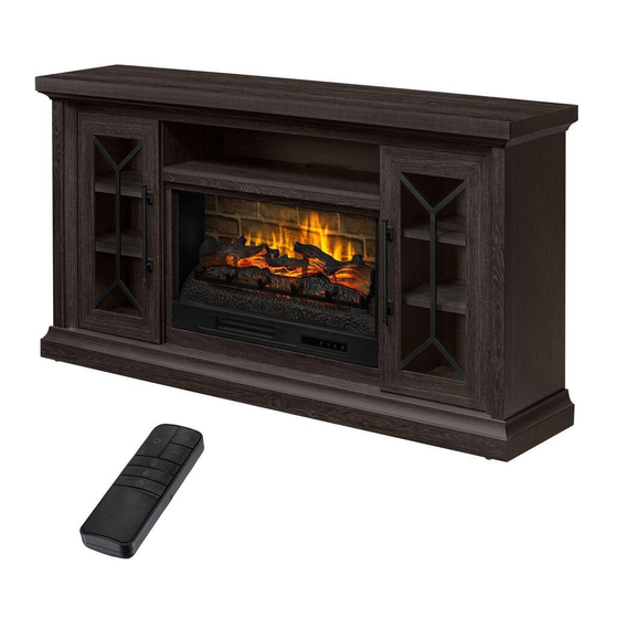
Madison 68in Media Console Infrared Electric Fireplace
We appreciate the trust and confidence you have placed in Home Decorators Collection through the purchase of this fireplace console. We strive to
continually create quality products designed to enhance your home. Visit us online to see our full line of products available for your home
ASSEMBLY INSTRUCTIONS
Questions, problems, missing parts? Before returning to the store,
call Home Decorators Collection Customer Service
8 a.m. - 7 p.m., EST, Monday-Friday
9 a.m. - 6 p.m., EST, Saturday
1-800-986-3460
HOMEDEPOT.COM /HOMEDECORATORS
improvement needs. Thank you for choosing Home Decorators Collection!
OR
THANK YOU
Model # HDFP68-51E
HDFP68-51AE
HDFP68-51BE
Advertisement
Table of Contents

Subscribe to Our Youtube Channel
Related Manuals for Home Decorators Collection HDFP68-51E


Summary of Contents for Home Decorators Collection HDFP68-51E
- Page 1 THANK YOU We appreciate the trust and confidence you have placed in Home Decorators Collection through the purchase of this fireplace console. We strive to continually create quality products designed to enhance your home. Visit us online to see our full line of products available for your home...
-
Page 2: Table Of Contents
Table of Contents Table of Contents .............. 2 Hardware Included ..............3 Safety Information ............2 Package Contents ..............4 Maximum Recommended Weight Loads .........2 Assembly................5 Warranty ................2 Care and Maintenance ............. 25 Pre-Assembly ..............2 Caring for Wood Furniture ............25 Planning Assembly ..............2 Cleaning the Fireplace Trim ...........25 Tools Required .................2... -
Page 3: Hardware Included
Pre-Assembly (continued) HARDWARE INCLUDED NOTE: Hardware not shown to actual size. Part Description Quantity Part Description Quantity Insert screw 10+1 extra Handle Pan head screw 8+1 extra Handle bolt Large wood dowel 41+2 extra Shelf support 16+1 extra Small wood dowel 4+1 extra Rubber bumper 4+1 extra... -
Page 4: Package Contents
Pre-Assembly (continued) PACKAGE CONTENTS Part Description Quantity Part Description Quantity Heater Middle top crossbar Left upright arm Left side panel Right upright arm Left partition panel Connector strap Right partition panel Ember bed Right side panel Left log Middle stile Right log Support rail Firebox wall panel... -
Page 5: Assembly
Assembly Screwing the cam bolts NOTE: Do not fully tighten all bolts until you finish assembling all parts. Once assembled, go back and fully tighten all bolts. This will make the assembly easier. □ Unpack the unit and confirm that you have all the hardware and required parts. Assemble the unit on a carpeted floor or the empty carton to avoid any scratches. - Page 6 Assembly (continued) Attaching the middle stiles □ Glue two small wood dowels (DD) into the inner holes on each middle stile (V). □ Attach the middle stiles (V) to the partition panels (S and T) respectively with three short flat head screws (GG) per stile. Screwing the cam bolts □...
- Page 7 Assembly (continued) Gluing the wood dowels □ Glue the large wood dowels (CC) into the inner holes on the partition panels (S and T) as shown. Gluing the wood dowels □ Glue the large wood dowels (CC) into the inner holes on the media shelf (L) and middle crossbars (Q and B1) as shown. HOMEDEPOT.COM/HOMEDECORATORS Please contact 1-800-986-3460 for further assistance.
- Page 8 Assembly (continued) Attaching the middle top crossbar NOTE: Refer to the cam lock assembling guide drawings in this step for further clarification on how to properly install cam locks. Apply this method whenever instructed to install cam locks □ Attach the middle top crossbar (Q) to the media shelf (L) by engaging four cam locks (EE). The cam locks face inward The cam lock assembling guide Attaching the partition panels...
- Page 9 Assembly (continued) Screwing the cam bolts □ Securely screw the cam bolts (FF) into the designated small holes on the top face of bottom panel (M) using a Phillips screwdriver. Attaching the support rails □ Glue two large wood dowels (CC) into the inner holes on each support rail (W). □...
- Page 10 Assembly (continued) Screwing the cam bolts □ Securely screw the cam bolts (FF) into the designated small holes on the top panel (K), bottom face of bottom panel (M) and bottom front stretcher (O) using a Phillips screwdriver. Attaching the top front molding □...
- Page 11 Assembly (continued) Gluing the wood dowels □ Glue the large wood dowels (CC) into the inner holes on the bottom panel (M) and bottom stretchers (N and O) as shown. Attaching the bottom front stretcher □ Attach the bottom front stretcher (O) to the bottom panel (M) by engaging four cam locks (EE). HOMEDEPOT.COM/HOMEDECORATORS Please contact 1-800-986-3460 for further assistance.
- Page 12 Assembly (continued) Attach the bottom supports □ Glue one large wood dowel (CC) into the end hole on each bottom support (X). □ Attach the bottom supports (X) to the bottom front stretcher (O) by engaging two cam locks (EE). Attaching the bottom rear stretcher □...
- Page 13 Assembly (continued) Fasten the bottom rear stretcher □ Using the pilot holes as a guide, fasten the bottom rear stretcher (N) to the bottom supports (X) with four medium flat head screws (HH). Attaching the bottom panel □ Using the wood dowels as guide, firmly press the assembled partition panels (S and T) and middle lower crossbar (B1) to the bottom panel (M) and fasten them in place with seven long flat head screws (II).
- Page 14 Assembly (continued) Attaching the side panels □ Align the large holes on both side panels (R and U) with the inserted wood dowels (CC) and press them together. Attach the side panels (R and U) in place by engaging eight cam locks (EE). Attaching the top panel □...
- Page 15 Assembly (continued) Installing the floor levelers □ Screw the floor levelers (SS) into the threaded inserts on the bottom front stretcher (O) and set to the correct height. □ Now, go back and securely tighten all the cam locks and screws. Make sure all the parts are tight and there are no gaps between the parts.
- Page 16 Assembly (continued) Installing the door hinges □ Extend two door hinges (KK) and rest the hinge cups onto the cutouts of each door (Y). Secure the door hinges (KK) in place by using two zinc screws (LL) in each. Attaching the door panels □...
- Page 17 Assembly (continued) Attaching the adjustable shelves □ Open the doors and insert eight shelf supports (OO) in the holes at the desired height inside each side compartment. Make sure you place the four shelf supports at the same level, so the shelf is not tilted. Tilt and rest the adjustable shelves (D1) onto the shelf supports.
- Page 18 Assembly (continued) Putting paper stickers □ Put the paper stickers (TT) onto the visible cam locks to conceal the cams. □ Stick the rubber bumpers (PP) on the outer corners of doors where meet the partition panels (S and T). Attaching upright arms IMPORTANT NOTE: .
- Page 19 Assembly (continued) Attaching logs to ember bed IMPORTANT: Carefully follow the 2 steps below for inserting each log. Install left log (F) into left hole of ember bed (E) by inserting front edge of base of the log into front notches of ember bed hole.
- Page 20 Assembly (continued) Attaching wall panel □ Fold the wall panel (H) as shown. Then position yourself at back side of heater (A). □ Hold wall panel (H) at the angle shown below and insert lower back edge into metal slots on back of heater (A). □...
- Page 21 Assembly (continued) Inserting the glass □ Slide the glass (I) into the inner U-channels on both upright arms (B and C) until the glass sits onto the heater (A). Make sure the top of the glass (I) is flush with the top of both upright arms (B and C). The warning labels on glass should face outward NOTE: If needed,...
- Page 22 Assembly (continued) Attaching connector strap □ Fasten connector strap (D) to both upright arms (B and C) using two screws (AA) as show below. Holes must be in line for screw to pass through. Finishing fireplace insert assembly □ The firebox is now ready for the next assemble step.
- Page 23 Assembly (continued) Installing the fireplace insert □ Lift the fireplace insert carefully into the back of the assembled mantel and centre it on the support rails in the opening. Use the pilot holes as a guide, fasten two mending plates (QQ) onto the firebox support (E1) with four pan head screws (BB) . Make □...
- Page 24 Assembly (continued) Interchanging the wood door panels □ To change door panels, loosen the screws on the inside of the door and rotate the clips to remove the panel. Replace with the desired panel, then rotate clips to secure the panel within the door frame and tighten screws. NOTE: The glass door panels are pre-attached when shipping.
-
Page 25: Care And Maintenance
Care and Maintenance A touch-up pen has been provided to minimize the small nicks or scratches that may occur during assembly or shipping. To clean and care for your furniture: □ Use a soft, clean cloth that will not scratch the surface when dusting. □... - Page 26 Questions, problems, missing parts? Before returning to the store, call Home Decorators Collection Customer Service 8 a.m. - 7 p.m., EST, Monday-Friday 9 a.m. - 6 p.m., EST, Saturday 1-800-986-3460 HOMEDEPOT.COM/HOMEDECORATORS Retain this manual for future use.
Need help?
Do you have a question about the HDFP68-51E and is the answer not in the manual?
Questions and answers