HBX CPU-0500 Installation Manual
Central processing unit
Hide thumbs
Also See for CPU-0500:
- Quick & easy set-up manual (2 pages) ,
- Quick start up manual (2 pages)

Related Manuals for HBX CPU-0500


Summary of Contents for HBX CPU-0500
- Page 1 Installation Manual Central Processing Unit 0500 Version 2.50 Mixing • Boiler Staging • Differential Setpoint • Geothermal • Pump Sequencer CPU-0500 HBX Control Systems Inc.
-
Page 2: Table Of Contents
Wiring & Installation ................4 Wiring ....................... 4 Jumper ....................4 Dipswitch ....................4 Installation ....................4 Programming CPU-0500 ................. 5-19 Multicolour Backlit Display ..............5 Dial Operation & Set/Status Mode ............6 Programming Scroll Mode ..............6 Programming Change Mode ..............6 Control Mode .................. -
Page 3: Introduction
This action may cause personal injury or have adverse effects on the installation process if V e r s i o n 2 . 5 0 The HBX CPU-0500 is a microprocessor based handled incorrectly. controller and as such is not to be regarded as a safety (limit) control. -
Page 4: Description
As a Mixing Control, the CPU-0500 has the capability to run a single On/Off or modulating boiler. Mixing types include Modulating Mixing, PMIp or Floating Action. Boiler Control The use of the CPU-0500 as a Boiler Control allows the capability to run up to two On/Off boilers, or a single modulating boiler with DHW requirements. Differential Setpoint Control The CPU-0500, when selected as a Setpoint Control, will allow for Dual or Differential Setpoint requirements. -
Page 5: Technical Data And Dimensions
Sensor (2) Heat Outdoor Heat Reversing Cooling Pump 1 Sensor Pump 2 Valve Demand / Backup DIMENSIONS Side View Front View Rear View Top View 70mm 66mm 168mm Bottom View 63.2mm 86mm 100mm © HBX Control Systems Inc. 2013 Page 3... -
Page 6: Wiring & Installation
Supply Power 120 VAC Installation The CPU-0500 is designed to be wall mounted, DIN rail mounted or installed in a separate electrical enclosure. The unit should be mounted inside and protected from falling water and high humidity conditions. With all the covers in place it is designed to protect any individual from accidental electrical shock. -
Page 7: Programming Cpu-0500
PROGRAMING MULTICOLOUR BACKLIT DISPLAY The Multicolour Backlit Display is one of the key features of the HBX Controls stand-alone CPU-0500 Control. Depending on which mode of operation is selected the screen colour will change to indicate information about the status of the system. -
Page 8: Dial Operation & Set/Status Mode
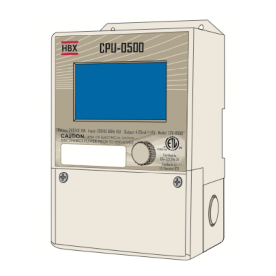
There are 2 modes for the control, programming and status screens. The programming screen is identified by the SET icon on the top/middle left corner. The status screen is indicated by the STATUS icon the top/middle left corner. CPU-0500 Input: 120VAC 60Hz 10A Output: 4-20mA/1-10V 1 10V... -
Page 9: Control Mode
The programming instructions for the CPU-0500 are broken down into the five control modes listed below. When the control is first plugged in you are asked to select which control mode you would like your CPU-0500 to operate in. To select your control mode simply turn the dial to the left or right to select the correct mode then wait five seconds to accept your selection. -
Page 10: Programming The Control
REPROGRAMMING THE CONTROL To reprogram the control for a different mode simply unplug the control and wait ten seconds before plugging the control back in. This will allow you to manually select a different mode for the control. The control will not reset to factory defaults. -
Page 11: Mixing Control Programming
► MIXING CONTROL PROGRAMMING Design Boiler Temperature This is the design boiler temperature. It is used in the outdoor reset design calculation and is 190.0 also the maximum setting for the boiler. (50°F to 200°F) Default: 190°F Boiler Temp Design Low Temperature System Temperature This is the design low temperature system temperature. - Page 12 Refer to Diagram #7 Single On/Off Boiler with Injection Diff Warm Weather Shut Down (WWSD) This setting is used to set the temperature at which the CPU-0500 will go into WWSD. Above 75.0 this temperature the system will be shut off.
- Page 13 (ON/OFF Default: OFF Time Heat Demand Heat 1) ON: This setting indicates that the CPU-0500 is in a permanent heat demand. Use instead off. of attaching a thermostat. 2) OFF (ON/OFF) Default: OFF Celsius &...
-
Page 14: Boiler Control Programming
Eg.) 6°F differential would be 3°F above and 3°F below. Boiler Diff Warm Weather Shut Down (WWSD) This setting is used to set the temperature at which the CPU-0500 will go into WWSD. Above 75.0 this temperature the system will be shut off. (20°F to 150°F) Default: 75°F... - Page 15 Screen Not Applicable in Boiler Two Stage Mode: DHW Target This setting is used to set the desired DHW tank temperature. 130.0 (OFF/1°F to 200°F) Default: 130 °F Refer to Diagram #3 Single Modulating Boiler with DHW or #4 Single On/Off Boiler with DHW.
- Page 16 (ON/OFF) Default: OFF Time Heat Demand Heat 1) ON: This setting indicates that the CPU-0500 is in a permanent heat demand. Use instead off. of attaching a thermostat. 2) OFF (ON/OFF) Default: OFF Celsius &...
-
Page 17: Differential Setpoint Programming
► DIFFERENTIAL SETPOINT PROGRAMMING Celsius & Fahrenheit Use this setting to change the display format from °C to °F. °F (°C/°F) Default: °F Setpoint 1 Differential This setting is used to set the differential between setpoint 2 temperature and setpoint 1 10.0 temperature. -
Page 18: Geothermal Control Programming
Eg.) 6°F differential would be 3°F above and 3°F below. Diff Cold Weather Shut Down This setting is used to set the temperature at which the CPU-0500 will go into CWSD. Below 75.0 °F this temperature the system will not allow the control to instigate cooling mode. - Page 19 Warm Weather Shut Down (WWSD) This setting is used to set the temperature at which the CPU-0500 will go into WWSD. Above 70.0 °F this temperature the system will not allow the control to instigate heating mode. (20°F to 150°F) Default: 70°F...
- Page 20 Backup Differential This setting can be used with the USE Backup Temperature or on its own to bring the backup 20.0 °F on. This setting is used to set a differential on the tank at which you would like the backup to come on.
-
Page 21: Pump Sequencer
► PUMP SEQUENCER Sequence Time This setting is used to set the rotation time for the pumps. 72.0 (OFF/1 to 480 hours) Default: 72 hours Time System Sequence Cycle This setting is used to set the # of demands that are given before the pumps will rotate. (OFF or up to 500 rotations) Default: OFF Eg.) set to 20. -
Page 22: Sample Wiring And Diagrams
V e r s i o n 2 . 5 0 DRAWINGS (GEOTHERMAL) #1. Single Stage Heat Pump with Backup. This system uses a single tank for heating and cooling. Central Processing Unit THM-0200 Thermostat CPU-0500 DO NOT CONNECT 10 A 10 A 4-20mA POWER HERE... - Page 23 HERE HERE 24V AC TM TM BOILER Boiler Pump Boiler Sensor DHW Pump Sensor 24 V AC Use Aquastat when Outdoor no thermistor is Sensor availible in the tank 120 V AC © HBX Control Systems Inc. 2013 Page 21...
- Page 24 H B X C P U - 0 5 0 0 H V A C C o n t r o l V e r s i o n 2 . 5 0 DRAWINGS (BOILER) #5. Two Stage Boiler for use with two single stage boilers or one 2 stage boiler. The aquastat will only increase the boiler temperature for DHW.
- Page 25 Injection Pump Low Temp System Sensor 24 V AC Aquastat will raise the water temp in Outdoor the boiler to DHW. It Sensor will also give priority if needed. 120 V AC © HBX Control Systems Inc. 2013 Page 23...
- Page 26 V e r s i o n 2 . 5 0 DRAWINGS (MIXING) #8. Modulating Mixing is used when small injection pumps may not work. Modulating signal can run 3-4 way mixing valves or VFD’s on large pumps. CPU-0500 Central Processing Unit THM-0100 Thermostat...
- Page 27 High Temp Differencial Output Contact Mod Output Apply control signal Setpoint 1 when using the Sensor modulating differential mod output when heat Setpoint 2 demand starts. Sensor 24 V AC 120 V AC © HBX Control Systems Inc. 2013 Page 25...
- Page 28 H B X C P U - 0 5 0 0 H V A C C o n t r o l V e r s i o n 2 . 5 0 DRAWING (PUMP SEQUENCER) #11. Pump Sequencer Central Processing Unit CPU-0500 10 A 10 A 4-20mA 1-10v...
- Page 29 Limitation of Liability In no event will HBX be liable for any damages, including loss of data, loss of profits, costs of cover or other incidental, consequential or indirect damages arising out of the installation, maintenance, commissioning, performance, failure or interruption of an HBX product, however caused and on any theory of liability.
-
Page 30: Warranty Information
H B X C P U - 0 5 0 0 H V A C C o n t r o l V e r s i o n 2 . 5 0 NOTES: Page 28... - Page 31 H B X C P U - 0 5 0 0 H V A C C o n t r o l V e r s i o n 2 . 5 0 NOTES: © HBX Control Systems Inc. 2013 Page 29...
- Page 32 Phone: +1 (403) 720-0029 Fax: +1 (403) 720-0054 Email: inf o @ hbxcontrols.com Web: www.hbxcontrols.com Manual Version v3.7 HBX Control Systems Inc. 4516 - 112 Avenue SE © HBX Control Systems Inc. 2013 Calgary, AB Canada T2C 2K2...
Need help?
Do you have a question about the CPU-0500 and is the answer not in the manual?
Questions and answers