
Subscribe to Our Youtube Channel
Related Manuals for HBX ZON-0600


Summary of Contents for HBX ZON-0600
- Page 1 Installation Manual ZON-0600 Version 1.0.0 • Zone Control ZON-0600 HBX Control Systems Inc.
-
Page 2: Table Of Contents
Control Systems Inc. H B X Z O N - 0 6 0 0 Z o n e C o n t r o l V e r s i o n 1 . 0 . 0 . 0 TABLE OF CONTENTS Introduction .................... -
Page 3: Introduction
ZON-0600. Each ZON-0600 can run one (1) fan coil each with humidity. FEATURES This control can also function as a stand alone system •... -
Page 4: Safety Symbols & Warnings
For more information go to www.P65Warnings.ca.gov. EXTREME HAZARD: The HBX ZON-0600 is a microprocessor based controller and as such is not to be regarded as a safety (limit) control. Please consult and install the heating or cooling appliance in accordance with the manufacturer’s recommendations. -
Page 5: Technical Data And Dimensions
V e r s i o n 1 . 0 . 0 TECHNICAL DATA AND DIMENSIONS TECHNICAL DATA AND DIMENSIONS Specifications: ZON-0600 TECHNICAL DATA 4 x THM-0600 Thermostat Communication inputs 3 x Fancoil outputs 24VAC 2A 1X Humidity output 24VAC 2A... -
Page 6: Wiring & Installation
This terminal is an input for an external thermistor 4. INPUT POWER to monitor any temperature or read outdoor temperature, or run a heating setpoint. This input is to power the ZON-0600. 0.5 Amps at 120 VAC is required to power this device. Page 4... -
Page 7: Installation
Thermostat field signal wiring installation The signal wiring that connects the ZON-0600 to each thermostat should not run parallel for any lengths with any other wires. If this is a retrofit installation and the thermostat signal wiring installation can not be verified it is recommended that the thermostats to be installed in the mechanical room with remote room (029-0022, not provided) and/or floor sensors (029-0045). -
Page 8: Main Screen Navigation
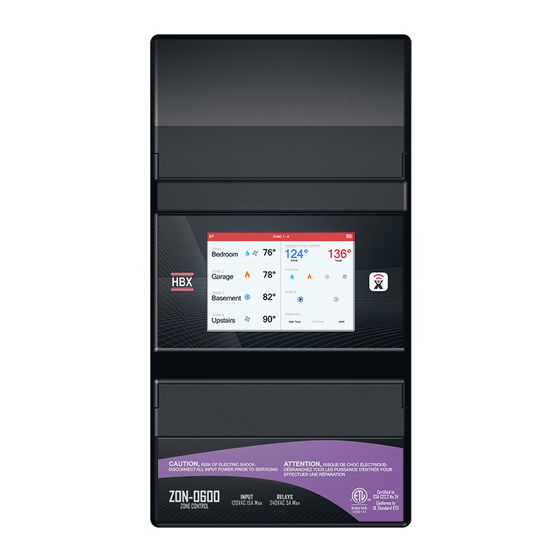
V e r s i o n 1 . 0 . 0 ZON-0600 MAIN SCREEN The ZON-0600 features a full LCD screen that will display each zone and what their current states are. Each THM-0600 will be displayed with their respective zone number, their name, current temp and if they have a demand for heating, cooling, fan or humidity. -
Page 9: System Settings
ZON-0600 and other ZON-0600’s have been LINKED. Secondary Stats – Sync code of any thermostats from Secondary Zone LINKED ZON-0600’s. This will only show up if this is the primary ZON-0600 and other ZON-0600’s have been LINKED. Secondary Stats... - Page 10 H B X Z O N - 0 6 0 0 Z o n e C o n t r o l V e r s i o n 1 . 0 . 0 DEMAND SETUP Demand 1 – This chosen demand will close the contact tt1 in the upper wiring chamber Demand 1 Demand 2 –...
- Page 11 H B X Z O N - 0 6 0 0 Z o n e C o n t r o l V e r s i o n 1 . 0 . 0 PUMP SETUP Pump 1 - The chosen pump type will close the lower contact at 1-2 (PUMP1) Pump choice options Pump 1 explained below...
- Page 12 Each sequence represents 4 Zone Sequence possible thermostats (THM-0600) per zone controller with a maximum of 5 ZON-0600’s in total. The first sequence will always be labelled Primary and represent sequence 1-4. Zone Control ID •...
- Page 13 H B X Z O N - 0 6 0 0 Z o n e C o n t r o l V e r s i o n 1 . 0 . 0 TIME SETTINGS Auto Time - When connected to a 2.4 GHz Network the time displayed on the THM-0600’s will be Auto Time associated with the time zone you have chosen.
- Page 14 Mode - Function of the auxiliary thermistor port at originate from the upper contacts EXT. THM. You can Mode choose from 3 options: Setpoint, Outdoor , Display. If you choose Setpoint, the ZON-0600 will display the following: Thermistor Target • Thermistor Target (Off, 35-200°F) this will be a heating only target for the Auxiliary thermistor input •...
- Page 15 H B X Z O N - 0 6 0 0 Z o n e C o n t r o l V e r s i o n 1 . 0 . 0 WWSD When the ZON-0600 is hooked up to the local Wi-Fi network, the control will use the local weather station Pump Setup ...
- Page 16 DAMPER SEQUENCES Damper Zone (Zone Setup) dampers can not be used in conjunction with 4-pipe mode. Damper theory can be shared between linked ZON-0600 devices. Single normally open (N/O) damper operation In a no heat or no cool situation there is no power to any of the dampers so they all remain in an open state.
-
Page 17: Application Drawing
TT2 Demand TT1 Demand Thermostat Demand Fancoil Fancoil Aux. Therm Signal Outputs Outputs Outputs Input Communication ZON-0600 Zone Control DO NOT CONNECT POWER HERE 9 10 11 12 13 14 ZONE POWER PUMP 1 PUMP 2 ZN 1 ZN 2... - Page 18 TT1 Heat Demand Fancoil Demand Fancoil Thermostat Signal Aux. Therm Outputs Outputs Outputs Communication Input ZON-0600 Zone Control DO NOT CONNECT POWER HERE Sensor *Not included with ZON- 0600 can use a 0029- 9 10 11 12 13 14 0045 ZONE...
- Page 19 H B X Z O N - 0 6 0 0 Z o n e C o n t r o l V e r s i o n 1 . 0 . 0 3) 2 Linked ZON-0600 Controls with THM-0600 and Zone Pumps and Valves Fancoil...
- Page 20 H B X Z O N - 0 6 0 0 Z o n e C o n t r o l V e r s i o n 1 . 0 . 0 4) ZON-0600 and CPU-0550 with THM-0600 and Zone Pumps To use external room thermistor,...
- Page 21 H B X Z O N - 0 6 0 0 Z o n e C o n t r o l V e r s i o n 1 . 0 . 0 5) ZON-0600 and ECO-0550 with THM-0600 and Zone Valves To use external room thermistor,...
- Page 22 H B X Z O N - 0 6 0 0 Z o n e C o n t r o l V e r s i o n 1 . 0 . 0 6) ZON-0600 with Zone Valves and Dampers Zone 5 and 7 are running 1...
- Page 23 H B X Z O N - 0 6 0 0 Z o n e C o n t r o l V e r s i o n 1 . 0 . 0 7) ZON-0600 Utilizing 4-Pipe and THM-0600 Zone 1...
-
Page 24: Troubleshooting Guides
Zones modules not linking • Check zone sequence on each module. • On any secondary ZON-0600, verify the primary ID is set correctly. • Ensure the zones modules are withing range. For additional assistance with the ZON-0550, please contact our Technical Support Department toll free at:... -
Page 25: Warranty Information
Limitation of Liability In no event will HBX be liable for any damages, including loss of data, loss of profits, costs of cover or other incidental, consequential or indirect damages arising out of the installation, maintenance, commissioning, performance, failure or interruption of an HBX product, however caused and on any theory of liability. - Page 26 H B X Z O N - 0 6 0 0 Z o n e C o n t r o l V e r s i o n 1 . 0 . 0 NOTES Page 24...
- Page 27 H B X Z O N - 0 6 0 0 Z o n e C o n t r o l V e r s i o n 1 . 0 . 0 NOTES Page 25...
- Page 28 Phone: +1 (403) 720-0029 Fax: +1 (403) 720-0054 Email: info@hbxcontrols.com Web: www.hbxcontrols.com Toll Free Technical Support: +1 (855) 410 2341 HBX Control Systems Inc. 4516 - 112 Avenue SE © HBX Control Systems Inc. 2021 Calgary, AB Canada T2C 2K2...
Need help?
Do you have a question about the ZON-0600 and is the answer not in the manual?
Questions and answers