Table of Contents
Advertisement
Quick Links
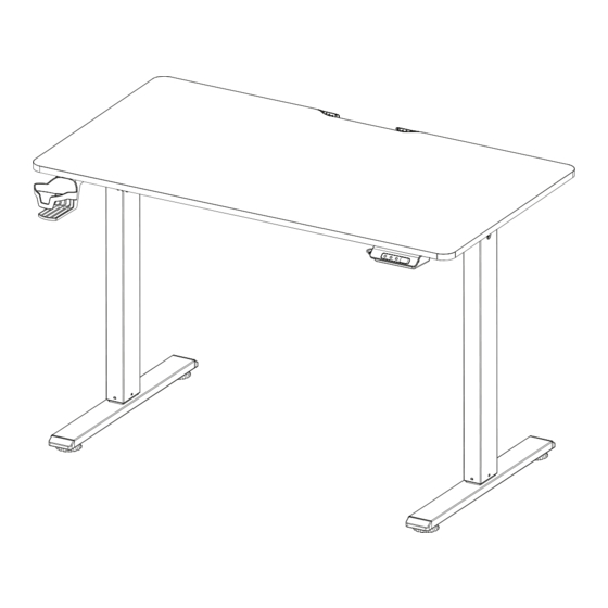
Assembly Instruction
Ergo 2 Series 43" x 24"
Scan to access the step-by-step
installation instructions and video.
SCREW ACCESSORIES
S1
S2
6mm Allen Key
x1
x1
3mm Allen Key
S7
S6
Foot Base & Motor
x9
Wire Clip
x3
Screw (M8)
PARTS ACCESSORIES
A
B
x2
Central Bracket
x2
Frame
G
F
Metal Rod
x1
Connector
Metal Rod #2
x1
K
L
x1
Keypad
Headphone Hook
x1
S3
S4
Bracket Screw
Metal Rod Connector
x12
x2
(M8)
Screw (M5)
S8
S9
Wood Screw
Footer
x4
x30
(M4)
C
D
x2
Motor
x1
Metal Frame Connector
H
I
J
x2
x2
Table Top
Foot Base
Side Bracket
M
N
Cup Holder
x1
Power Cord
x1
STEP 1
A*2
B
S5
x2
STEP 2
Frame Screw
x2
(M4)
B
C*2
E
x6
STEP 3
x1
Metal Rod #1
E
D
x1
F
O
x1
Cable Clip
x1
S3x2
x1
Make sure the Front labels are in the same direction.
S3x3
x1
E
F
x1
S3x3
F
E
Advertisement
Table of Contents

Related Manuals for MotionGrey Ergo 2 Series


Summary of Contents for MotionGrey Ergo 2 Series
- Page 1 STEP 1 Assembly Instruction S3x2 Ergo 2 Series 43" x 24" Scan to access the step-by-step installation instructions and video. SCREW ACCESSORIES Make sure the Front labels are in the same direction. STEP 2 Bracket Screw Frame Screw Metal Rod Connector...
- Page 2 STEP 4 STEP 7 S4x2 S9x4 STEP 5 STEP 8 S3x2 S9x26 S3x2 S7x3 STEP 6 STEP 9 S8x2 S6x4 S6x4 S8x2 After the table is installed, please press the RST key to start. Please ensure that the table legs are aligned vertically with the connecting point.
Need help?
Do you have a question about the Ergo 2 Series and is the answer not in the manual?
Questions and answers