Advertisement
Table of Contents
- 1 Table of Contents
- 2 Part 1 - Overview Specs Overview
- 3 Dimensions
- 4 Package
- 5 FC & ESC Connection
- 6 Part 2 - Speedybee F405 V4 Flight Controller
- 7 Layout
- 8 Fc's Peripheral Connection
- 9 App & FC Configuration
- 10 FC Firmware Update
- 11 Specifications
- 12 Part 3 - Speedybee BLS 55A 4-In-1 ESC Layout
- 13 ESC Configuration
- 14 ESC Firmware Update
- 15 Specifications
- Download this manual
F405 V4 BLS 55A 30x30 Stack
Contents
Connection with Motors & Power Cable
SpeedyBee
User Manual V1.0
(Click on any section to jump)
1
2
3
4
5
6
7
8
9
10
11
12
13
14
Advertisement
Table of Contents

Related Manuals for SpeedyBee F405 V4 BLS 55A 30x30 Stack


Summary of Contents for SpeedyBee F405 V4 BLS 55A 30x30 Stack
-
Page 1: Table Of Contents
(Click on any section to jump) Part 1 - OverView Specs Overview Dimensions Package FC & ESC Connection Part 2 - SpeedyBee F405 V4 Flight Controller Layout FC’s Peripheral Connection App & FC Configuration FC Firmware Update Specifications Part 3 - SpeedyBee BLS 55A 4-in-1 ESC Layout Connection with Motors &... -
Page 2: Part 1 - Overview Specs Overview
Part 1 - OverView Specs Overview 1/14 SpeedyBee F405 V4 BLS 55A 30x30 Stack Product Name SpeedyBee F405 V4 Flight Controller SpeedyBee BLS 55A 4-in-1 ESC Supported. For FC & ESC parameter settings Bluetooth NOT Supported Wireless FC Firmware Flashing... -
Page 3: Dimensions
Dimensions 2/14 1.6mm 39.4mm 1.6mm 44mm 7.8mm 30.5mm 30.5mm 16.1mm... -
Page 4: Package
3/14 Package Option 1 - SpeedyBee F405 V4 55A 30x30 Stack SpeedyBee F405 V4 Flight Controller x 1 SpeedyBee BLS 55A 4-in-1 ESC x 1 35V 1000uF Low ESR Capacitor x 1 M3 Nylon Nut x 5 M3 silicone O Ring x 5 M3*8mm Silicone Grommets(for FC) x 5 M3*8.1mm Silicone Grommets(for ESC) x 5... - Page 5 Option 2 - SpeedyBee F405 V4 Flight Controller SpeedyBee F405 V4 Flight Controller x 1 M3*8mm Silicone Grommets(for FC) x 5 SH 1.0mm 30mm-length 8pin Cable(for FC-ESC connection) x 1 DJI 6pin Cable(80mm) x 1 Option 3 - SpeedyBee BLS 55A 4-in-1 ESC...
-
Page 6: Fc & Esc Connection
FC & ESC Connection 4/14 Use the 8-pin cable in the package to connect the FC and the ESC. Or solder 8 wires directly to the 8 pads on each end. Method 1 - Using 8-pin cable Use any end of the 8-pin JST cable to connect the FC to the ESC. F405 V4 Flight Controller BLS 55A 4-in-1 ESC Method 2 - Direct soldering... -
Page 7: Part 2 - Speedybee F405 V4 Flight Controller
Part 2 - F405 V4 Flight Controller Layout 5/14 For Second 4-in-1 ESC Receiver FPV Cam Barometer Extra PWM output Antenna MCU: F405 Bluetooth Chip Orange LED USB TYPC-C Port 4-level LED battery indicator Red LED Green LED Blue LED BOOT Button 5V 3A BEC Gyro(ICM42688P) - Page 8 LED strips connected to LED1-LED4 pads on the corners. Short-press the BOOT button to cycle the LED displaying mode. Long-press the BOOT button to switch between SpeedyBee-LED mode and BF-LED mode. Under BF-LED mode, all the LED1-LED4 strips will be controlled by the Betaflight firmware.
-
Page 9: Fc's Peripheral Connection
FC’s Peripheral Connection 6/14 Spektrum ELRS Receiver Receiver PPM Receiver SBUS Receiver SBUS 5-36V 5-36V 5-36V Video Video Video G/TX Crossfire Nano Rx Menu M/RX Menu CH2 RX CH1 TX SIGNAL SERVO LED Strip Buzzer Analog VTX DJI Air Unit... - Page 10 Motor 4 Motor 2 Motor 3 Motor 1 1000uF Low ESR Capacitor XT60 Power Cable Note1: In order to prevent the stack from being burnt out by voltage spikes on powering up, it is strongly recommended to use the Low ESR capacitor in the package.
- Page 11 Cable Connection vs DJI O3 Air Unit Use 6-pin cable comes with the O3 Air Unit Cable Connection vs RunCam Link/ Caddx Vista Air Unit Use 6-pin cable comes with the F405 V4 stack (See the accessory No.11 in the package section) SBUS 7.4-26.4V Cable Connection vs DJI Air Unit V1...
- Page 12 Importance notice for SBUS receiver When using an SBUS receiver, the SBUS signal wire of the receiver must be connected to the SBUS pad on the front side of the flight controller (this pad internally uses UART2). If you are also using the DJI Air Unit(O3/Link/Vista/Air Unit V1), you will need to disconnect the SBUS signal wire from the Air Unit harness.
-
Page 13: App & Fc Configuration
App & FC Configuration 7/14 Get the SpeedyBee App Search ‘SpeedyBee’ on Google Play or App Store. Or download the Android .apk file on our website: https://www.speedybee.com/download. FC Configuration... -
Page 14: Fc Firmware Update
FC Firmware Update 8/14 SpeedyBee F405 V4 flight controller does not support wireless firmware flashing, so please flash firmware for it on your PC following the steps below: ① Connect the flight controller to the PC with a USB cable ② Open Betafight/ INAV configurator on your PC. Take Betaflight configurator as an example, go to the ‘Firmware Flashing’... -
Page 15: Specifications
SD cards or buy the tested cards from our store. Supported. For SpeedyBee BLS 55A ESC, please set scale = 400 and Offset = 0. Current Sensor Input Power Input 3S - 6S Lipo(Through G, BAT pins/pads from the 8-pin connector or 8-pads on the bottom side) -
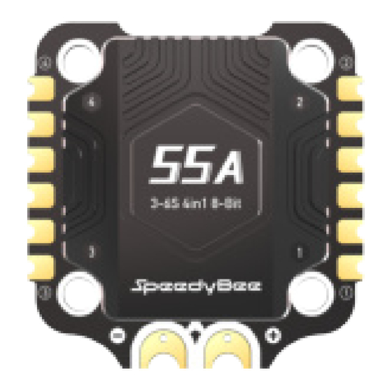
Page 16: Part 3 - Speedybee Bls 55A 4-In-1 Esc Layout
Part 3 - SpeedyBee BLS 55A 4-in-1 ESC Layout 10/14 MOTOR 4 MOTOR 2 MOTOR 1 MOTOR 3 Capacitor pin Capacitor pin BAT+ BAT- hole(GND) hole(BAT+) 8pin connector(to FC) Driver Chips MCU(BB21) TVS Diode... - Page 17 Connection with the flight controller & Motors 11/14 Motor 4 Motor 2 Motor 3 Motor 1 1000uF Low ESR Capacitor XT60 Power Cable Note1: In order to prevent the stack from being burnt out by voltage spikes on powering up, it is strongly recommended to use the Low ESR capacitor in the package.
-
Page 18: Esc Configuration
ESC Configuration 12/14 You could use the SpeedyBee APP to configure this ESC wirelessly for both BLHeli_S or Bluejay firmware. Steps: You could also use PC configurators to configure this ESC. We recommend the ESC Configurator. Please use Google Chrome browser and visist:... -
Page 19: Esc Firmware Update
ESC Firmware Update 13/14 This 8-bit 55A ESC can run BLHeliS or Bluejay firmware. It is loaded with BLHeliS firmware by default. You could also flash it to Bluejay firmware which can support RPM filtering and Bi-directional Dhsot. Firmware flashing steps are as follows: ●... -
Page 20: Specifications
Specifications 14/14 Product Name SpeedyBee BLS 55A 30x30 4-in-1 ESC Firmware BLHeli_S J-H-40 Wireless Configuration Full Configuration Supported in the SpeedyBee app PC Configurator Download Link https://esc-configurator.com/ Continuous Current 55A * 4 Burst Current 70(10 seconds) TVS Protective diode External Capacitor...
Need help?
Do you have a question about the F405 V4 BLS 55A 30x30 Stack and is the answer not in the manual?
Questions and answers