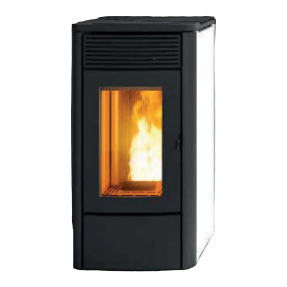
MCZ ALYSSA AIR 6 M1 Use And Installation Manual
Sealed pellet stove
Hide thumbs
Also See for ALYSSA AIR 6 M1:
- Use and installation manual (64 pages) ,
- Use and installation manual (56 pages) ,
- Operation and cleaning (72 pages)

Subscribe to Our Youtube Channel
Related Manuals for MCZ ALYSSA AIR 6 M1


Summary of Contents for MCZ ALYSSA AIR 6 M1
- Page 1 USE AND INSTALLATION MANUAL SEALED PELLET STOVE TECLA AIR 6 M1 ALYSSA AIR 6 M1 PART 1 - REGULATIONS AND ASSEMBLY Instructions in English...
-
Page 2: Table Of Contents
TABLE OF CONTENTS TABLE OF CONTENTS ....................II INTRODUCTION ......................1 1-WARNINGS AND WARRANTY CONDITIONS ..............2 2-INSTALLATION ......................8 3-DRAWINGS AND TECHNICAL FEATURES ..............17 4-UNPACKING ......................20 5-ALYSSA STOVE ASSEMBLY/DISASSEMBLY ..............23 6-TECLA STOVE ASSEMBLY/DISASSEMBLY ..............37 7-DOOR OPENING .....................46 8-CONNECTIONS TO ADDITIONAL DEVICES ..............47 9-LOADING THE PELLETS ...................49... -
Page 3: Introduction
No part of this manual may be translated into other languages, adapted and/or reproduced, even in part in other mechanical and/or electronic form or media, for photocopies, recordings or other, without the prior written authorisation from MCZ Group Spa. The company reserves the right to make changes to the product at any time without prior notice. The proprietary company reserves its rights according to law. -
Page 4: 1-Warnings And Warranty Conditions
1-WARNINGS AND WARRANTY CONDITIONS SAFETY WARNINGS • Installation, electrical connection, operating check and maintenance must only be carried out by authorised and qualified personnel. • Install the product in accordance with all local and national legislation and regulations in force in the region or state. • Only use the fuel recommended by the manufacturer. - Page 5 1-WARNINGS AND WARRANTY CONDITIONS • Do not dry linen on the product. Any drying racks or the like must be kept at a safe distance from the product. Fire hazard. • All liability for improper use of the product is entirely borne by the user and relieves the manufacturer of any civil and criminal liability.
- Page 6 1-WARNINGS AND WARRANTY CONDITIONS • It is recommended not to remove the feet that support the product in order to ensure adequate insulation, especially if the flooring is made of flammable materials. • In the event of a malfunction of the ignition system, do not force it on by using flammable materials.
- Page 7 1-WARNINGS AND WARRANTY CONDITIONS INFORMATION: Please contact the retailer or qualified personnel authorised by the company to resolve a problem. • Only use the fuel specified by the manufacturer. • When the product is switched on for the first time, it is normal for it to emit smoke due to the paint heating for the first time. Therefore make sure the room in which it is installed is well ventilated.
- Page 8 1-WARNINGS AND WARRANTY CONDITIONS WARRANTY CONDITIONS The company guarantees the product, with the exception of parts subject to normal wear (listed on the following page), for a period of 2 (two) years from the date of purchase attested by: • a document to serve as proof of purchase (invoice and/or receipt) that shows the name of the vendor and the date on which the purchase was made;...
- Page 9 1-WARNINGS AND WARRANTY CONDITIONS Without prejudice to the legal or regulatory limits, the warranty does not cover the containment of atmospheric and acoustic pollution. The company declines all liability for any damage which may be caused, directly or indirectly, to persons, animals or objects as a consequence of non-compliance with any provision specified in the manual, especially warnings regarding installation, use and maintenance of the appliance.
-
Page 10: 2-Installation
2-INSTALLATION The instructions in this chapter refer explicitly to the Italian installation regulation UNI 10683. In any case, always observe the regulations in force in the country of installation. PELLETS Wood pellets are manufactured by extruding sawdust which is produced during the processing of natural dried wood (without paint). The compactness of the material is guaranteed by the lignin contained in the wood itself and allows the pellets to be produced without glue or binders. - Page 11 If the floor is made of wood, it is recommended to fit a floor protection sheet in compliance with the standards in force in the country of installation. Non-flammable walls Flammable walls ALYSSA AIR 6 M1 A = 5 cm A = 5 cm B = 5 cm...
- Page 12 2-INSTALLATION FOREWORD The Flue chapter has been drawn up with reference to the provisions of European Standards (EN13384 - EN1443 - EN1856 - EN1457). The chapter provides indications for installing an efficient and correct flue but is under no circumstances to substitute the regulations in force, which the qualified manufacturer must be in possession of.
- Page 13 2-INSTALLATION TECHNICAL SPECIFICATIONS Have the efficiency of the flue checked by an authorised technician. The flue must be sealed against flue gases, in a vertical direction without narrowing, be made with materials impermeable to smoke, condensation, thermally insulated and suitable to resist normal mechanical stress over time (we recommend fireplaces made of A/316 or refractory material with insulated round section double chamber).
- Page 14 2-INSTALLATION ROOF AT 60° ROOF AT 45° 45° 60° A = MIN. 2.60 metres A = MIN. 2.00 metres FIGURE 5 FIGURE 6 B = DISTANCE > 1.20 metres B = DISTANCE > 1.30 metres C = DISTANCE < 1.20 metres C = DISTANCE <...
- Page 15 2-INSTALLATION MAINTENANCE The flue must be kept clean, since the deposit of soot or unburnt oils reduces the cross-section, blocking the draught and thus compromising the efficient operation of the stove and, if large build-ups accumulate, can catch fire. The flue and chimneypot must be cleaned and checked by a qualified chimney sweep at least once a year.
- Page 16 2-INSTALLATION EXTERNAL AIR INLET It is mandatory to provide an adequate external air inlet that supplies the combustion air required for the product to work properly. The flow of air between the outside and the installation room may be direct, through an inlet in an external wall of the room (preferable solution see Figure 9 a), or indirect, via air intake from adjoining rooms and connecting permanently with the installation room (see Figure 9 b).
- Page 17 2-INSTALLATION DISTANCE (metres) The air inlet must be at a distance of: 1.5 m BELOW Doors, windows, smoke outlets, cavities, ..1.5 m HORIZONTALLY Doors, windows, smoke outlets, cavities, ..0.3 m ABOVE Doors, windows, smoke outlets, cavities, ..1.5 m AT A DISTANCE from smoke outlet CONNECTION TO THE FLUE...
- Page 18 2-INSTALLATION EXAMPLES OF CORRECT INSTALLATION 1. Installation of Ø120mm flue with hole for the passage of the pipe increased by: minimum 100mm around the pipe if next to non- flammable parts such as cement, brick, etc.; or minimum 300mm around the pipe (or as required by plate data) if next to flammable parts such as wood etc.
-
Page 19: 3-Drawings And Technical Features
3-DRAWINGS AND TECHNICAL FEATURES DRAWINGS AND CHARACTERISTICS ALYSSA AIR 6 M1 STOVE DIMENSIONS Ø48 Ø80 152 124 Ø80 Technical Dept. - All rights reserved - Reproduction prohibited... - Page 20 3-DRAWINGS AND TECHNICAL FEATURES TECLA AIR 6 M1 STOVE DIMENSIONS Ø48 Ø80 Ø80...
- Page 21 3-DRAWINGS AND TECHNICAL FEATURES TECHNICAL SPECIFICATIONS TECLA AIR 6 M1/ALYSSA AIR 6 M1 Energy Efficiency Class Nominal output power 6.3 kW (5418 kcal/h) Minimum output power 2.5 kW (2150 kcal/h) Efficiency at Max 91.5% Efficiency at Min 92.0% Temperature of exhaust smoke at Max 165 °C...
-
Page 22: 4-Unpacking
4-UNPACKING PREPARATION AND UNPACKING The packaging consists of a recyclable cardboard box in line with RESY standards and a wooden pallet. All packaging materials can be reused for similar use or eventually disposed of as urban solid waste, in compliance with the regulations in force. After having removed the packaging make sure the product is intact. - Page 23 4-UNPACKING Remove the stoves from the pallet by removing the two screws “u” and the plate “s” from the stove foot. There are four brackets “s”. REMOVE THE FIREBOX CAST IRON PANEL CARD- BOARD REMOVING THE FASTENING BRACKETS Technical Dept. - All rights reserved - Reproduction prohibited...
- Page 24 4-UNPACKING Position the stove and connect it to the flue. Use the 4 adjustable feet (J) to get the stove correctly levelled so that the smoke outlet is lined up with the connecting pipe. If the stove needs to be connected to an outlet pipe which goes through the rear wall (to connect to the flue), take utmost care to make sure that the joint is not forced.
-
Page 25: 5-Alyssa Stove Assembly/Disassembly
5-ALYSSA STOVE ASSEMBLY/DISASSEMBLY On delivery, the Alyssa stove has no ceramic cladding, as shown in the image below. Take the box with the ceramic panels and the hardware kit (figure below) and prepare them for installation. The ceramics are already completely assembled and ready to be installed on the stove. - Page 26 5-ALYSSA STOVE ASSEMBLY/DISASSEMBLY REMOVING THE TOP Lift the pellet loading door “L” and remove the top “H” from the structure.
- Page 27 5-ALYSSA STOVE ASSEMBLY/DISASSEMBLY DISASSEMBLING THE FRONT UPPER PANEL In the event of cleaning operations, it may be necessary to remove the upper front panel “ M “; proceed as follows: • Undo the two screws “k” and remove the upper front panel “M” •...
- Page 28 5-ALYSSA STOVE ASSEMBLY/DISASSEMBLY DISASSEMBLING THE FRONT LOWER PANEL In case of maintenance and/or interventions it is possible to remove the lower panel “P”. Proceed as follows: • Open the firebox door ”F” • Remove the two screws “x”...
- Page 29 5-ALYSSA STOVE ASSEMBLY/DISASSEMBLY • Lift the panel “P” so as to let out the pins “s” present in the structure, from the holes “v” on the lower panel “P” • place the panel in a safe place The lower panel “P” can also be removed with installed ceramic sides.
- Page 30 5-ALYSSA STOVE ASSEMBLY/DISASSEMBLY ALYSSA STOVE CERAMIC CLADDING ASSEMBLY Before mounting the ceramics it is necessary to mount the support profiles: • take the front profile “B” • insert the plugs “s” which are in the profile “B” in the holes “t” on the structure •...
- Page 31 5-ALYSSA STOVE ASSEMBLY/DISASSEMBLY • In the upper part of the stove structure, remove the two front and rear “u” screws and the “z” washers. • Hold the screws “u” and the washers “z” to fix the brackets in the following operations.
- Page 32 5-ALYSSA STOVE ASSEMBLY/DISASSEMBLY • Position the upper plate “D” above the structure and make sure that the holes “t”, on the plate “D”, enter the pins “s” on the front profile “B” positioned in the previous operations • do the same operation at the rear profile “C” •...
- Page 33 5-ALYSSA STOVE ASSEMBLY/DISASSEMBLY • At this point take a ceramic “A” and insert it between the two profiles “B” and “C”. • Accompany the ceramic “A” until it rests on the lower part of the stove structure Technical Dept. - All rights reserved - Reproduction prohibited...
- Page 34 5-ALYSSA STOVE ASSEMBLY/DISASSEMBLY • Place two felt inserts “G” in the upper profile of the ceramic panel “A”...
- Page 35 5-ALYSSA STOVE ASSEMBLY/DISASSEMBLY • Take another ceramic panel “A” and insert it between the profiles “B” and “C” paying attention to accompany it to the other ceramic Technical Dept. - All rights reserved - Reproduction prohibited...
- Page 36 5-ALYSSA STOVE ASSEMBLY/DISASSEMBLY • Take the bracket “E” and position them over the plate “D” to block the ceramics • Fix the bracket “E” using the screw “u” and the washer “z” always removed in the previous operations from the structure of the stove...
- Page 37 5-ALYSSA STOVE ASSEMBLY/DISASSEMBLY • Perform the same operations also for mounting the ceramics on the left side. Technical Dept. - All rights reserved - Reproduction prohibited...
- Page 38 5-ALYSSA STOVE ASSEMBLY/DISASSEMBLY • Take the top “H” and put it back on the stove, after lifting the pellet lid “L”...
-
Page 39: 6-Tecla Stove Assembly/Disassembly
6-TECLA STOVE ASSEMBLY/DISASSEMBLY On delivery, the TECLA stove has no metal cladding and with the top fitted, as shown in the image below. Take the box with the metal sides (figure below) and prepare them for installation. Attention! Carefully handle the metal sides as the paint may be damaged. POS. - Page 40 6-TECLA STOVE ASSEMBLY/DISASSEMBLY REMOVING THE TOP Lift the pellet loading door “L” and remove the top “H” from the structure.
- Page 41 6-TECLA STOVE ASSEMBLY/DISASSEMBLY DISASSEMBLING THE FRONT UPPER PANEL In the event of cleaning operations, it may be necessary to remove the upper front panel “ M “; proceed as follows: • Undo the two screws “k” and remove the upper front panel “M” •...
- Page 42 6-TECLA STOVE ASSEMBLY/DISASSEMBLY DISASSEMBLING THE FRONT LOWER PANEL In case of maintenance and/or interventions it is possible to remove the lower panel “P”. Proceed as follows: • Open the firebox door ”F” • Remove the two screws “x”...
- Page 43 6-TECLA STOVE ASSEMBLY/DISASSEMBLY • Lift the panel “P” so as to let out the pins “s” present in the structure, from the holes “v” on the lower panel “P” • place the panel in a safe place The lower panel “P” can also be removed with installed metal sides.
- Page 44 6-TECLA STOVE ASSEMBLY/DISASSEMBLY TECLA STOVE METAL HOUSING ASSEMBLY Take the right metal side “A” and insert the hooks “z” on the bottom of the panel into the holes “u” in the stove structure.
- Page 45 6-TECLA STOVE ASSEMBLY/DISASSEMBLY Now place the panel “E” near the structure and fix it with the screws “u” and the washers “z”. Technical Dept. - All rights reserved - Reproduction prohibited...
- Page 46 6-TECLA STOVE ASSEMBLY/DISASSEMBLY Proceed in the same way for mounting the left side “B”.
- Page 47 6-TECLA STOVE ASSEMBLY/DISASSEMBLY Take the top “H” and put it back on the stove, after lifting the pellet lid “L” Technical Dept. - All rights reserved - Reproduction prohibited...
-
Page 48: 7-Door Opening
7-DOOR OPENING OPENING THE DOOR OF THE FIREBOX To open the hearth door “F”, insert the handle (supplied) into the hole in the handle “P” and pull it towards you. Attention! Only open the door when the stove is off and cold. -
Page 49: 8-Connections To Additional Devices
8-CONNECTIONS TO ADDITIONAL DEVICES USB SOCKET There is a USB socket on the back of the stove, if a software update is required; the ceramic/metal parts do not have to be removed to reach the socket directly in the circuit board (pos. 5 in the PCB). Attention! The USB socket must be used by skilled technicians. - Page 50 8-CONNECTIONS TO ADDITIONAL DEVICES ELECTRICAL CONNECTION First connect the power cable to the back of the stove and then to a wall socket. It is recommended to disconnect the power cable when the stove is not used. The cable must never come into contact with the smoke exhaust pipe or any other part of the stove. ELECTRICAL STOVE CONNECTION STOVE POWER SUPPLY Connect the power cable to the back of the stove and then to a wall socket.
-
Page 51: 9-Loading The Pellets
9-LOADING THE PELLETS LOADING THE PELLETS Fuel is loaded from the upper part of the stove by lifting door “G”. Pour the pellets in slowly so that they are deposited at the bottom of the hopper. If loading pellets when the stove is running, open the door of the tank using the stove mitten that comes with the stove itself. - Page 52 MCZ GROUP S.p.A. Via La Croce n°8 33074 Vigonovo di Fontanafredda (PN) – ITALY Telephone: 0434/599599 a.s. Fax: 0434/599598 Internet: www.mcz.it e-mail: mcz@mcz.it 8901912100 REV.0 25/07/2019...
Need help?
Do you have a question about the ALYSSA AIR 6 M1 and is the answer not in the manual?
Questions and answers