Table of Contents
Advertisement
Quick Links
Advertisement
Table of Contents

Related Manuals for MCZ AMY Air


Summary of Contents for MCZ AMY Air
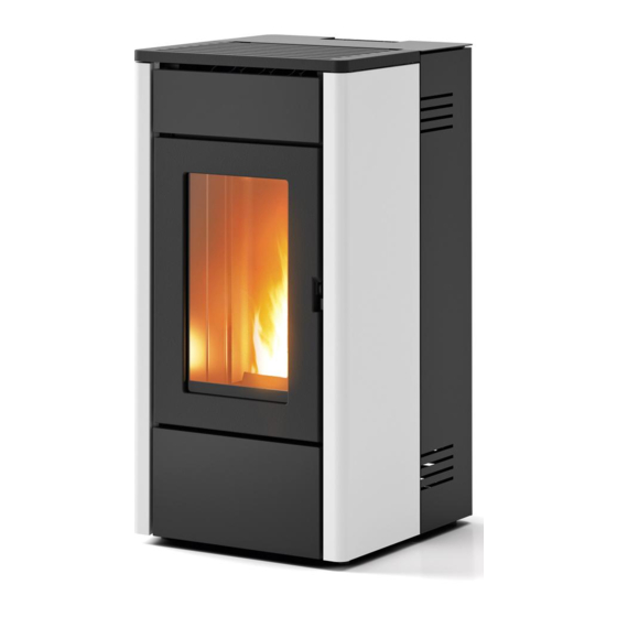
- Page 1 INSTALLATION GUIDE SEALED PELLET STOVE AMY Air Instructions in English...
-
Page 2: Table Of Contents
TABLE OF CONTENTS TABLE OF CONTENTS ....................II INTRODUCTION ......................1 1-WARNINGS AND WARRANTY CONDITIONS ..............2 2-INSTALLATION ......................8 3-DRAWINGS AND TECHNICAL FEATURES ..............17 4-INSTALLATION AND ASSEMBLY ................19 5-CONNECTION TO ADDITIONAL DEVICES ..............28 6-LOADING THE PELLETS ...................29 7-FIRST START-UP ....................30 8-CONTROL PANEL ....................31 9-OPERATION ......................38 10-SAFETY DEVICES ....................49 11-ALARMS ......................50... -
Page 3: Introduction
REVISIONS TO THE PUBLICATION The content of this manual is strictly technical and the property of MCZ Group Spa. No part of this manual may be translated into other languages and/or adapted and/or reproduced, even in part, in other mechanical or electronic forms, photocopies, recordings or other, without the prior written authorisation from MCZ Group Spa. -
Page 4: 1-Warnings And Warranty Conditions
1-WARNINGS AND WARRANTY CONDITIONS SAFETY PRECAUTIONS • Installation, electrical connection, function test and maintenance must only be carried out by authorised and qualified personnel. • Install the product in accordance with all local and national legislation and regulations in force in the region or state. •... - Page 5 1-WARNINGS AND WARRANTY CONDITIONS • Do not put linen on the product to dry. Any drying racks or the like must be kept at a safe distance from the product. Fire hazard. • All liability for improper use of the product is entirely borne by the user and relieves the Manufacturer from any civil and criminal liability.
- Page 6 1-WARNINGS AND WARRANTY CONDITIONS exposed to weathering. • It is recommended not to remove the feet that support the product in order to guarantee adequate insulation, especially if the flooring is made of flammable materials. • In the event of a malfunction of the ignition system, do not force it to light by using flammable materials.
- Page 7 1-WARNINGS AND WARRANTY CONDITIONS INFORMATION: Please contact the retailer or qualified personnel authorised by the company to resolve a problem. • You must only use the fuel specified by the manufacturer. • When the product is switched on for the first time it is normal for it to emit smoke due to the paint heating for the first time. Therefore make sure the room in which it is installed is well ventilated.
- Page 8 1-WARNINGS AND WARRANTY CONDITIONS EXCLUSIONS The warranty does not cover malfunctions and/or damage to the appliance that arise due to the following causes: • Damage caused during transportation and/or handling • all parts that develop faults due to negligence or improper use, incorrect maintenance, installation that does not comply with the manufacturer’s instructions (always refer to the installation guide provided with the appliance) •...
- Page 9 1-WARNINGS AND WARRANTY CONDITIONS SPARE PARTS In the event of a malfunction, consult the retailer who will forward the call to the Technical Assistance Department. Only use original spare parts. The retailer or service centre can provide all necessary information regarding spare parts. We do not recommend waiting for the parts to get worn out before having them replaced.
-
Page 10: 2-Installation
2-INSTALLATION The instructions in this chapter refer explicitly to the Italian installation regulation UNI 10683. In any case, always observe the regulations in force in the country of installation. PELLETS Wood pellets are manufactured by hot-extruding compressed sawdust which is produced during the working of natural dried wood. The compactness of the material is guaranteed by the lignin contained in the wood itself and allows pellets to be produced without glue or binders. - Page 11 If the floor is made of wood, it is recommended to fit a floor protection sheet in compliance with the Standards in force in the country of installation. Non-flammable walls Flammable walls AMY AIR A = 5 cm A = 5 cm B = 5 cm B = 5 cm If the floor is made of combustible material, it is recommended to use protection made of non-combustible material (steel, glass...) that...
- Page 12 2-INSTALLATION FOREWORD The Chimney Flue chapter has been drawn up with reference to the provisions of European Standards (EN13384 - EN1443 - EN1856 - EN1457). The chapter provides indications for installing an efficient and correct flue but is under no circumstances to substitute the regulations in force, which the qualified technician must be in possession of.
- Page 13 2-INSTALLATION TECHNICAL CHARACTERISTICS Have the efficiency of the flue checked by an authorised technician. The flue must be sealed against flue gasses, in a vertical direction without narrowing, be made with materials impermeable to smoke, condensation, thermally insulated and suitable to resist normal mechanical stress over time (we recommend fireplaces made of A/316 or refractory material with insulated round section double chamber).
- Page 14 2-INSTALLATION ROOF AT 60° ROOF AT 45° 45° 60° A = MIN. 2.60 metres A = MIN. 2.00 metres FIGURE 6 FIGURE 5 B = DISTANCE > 1.20 metres B = DISTANCE > 1.30 metres C = DISTANCE < 1.20 metres C = DISTANCE <...
- Page 15 2-INSTALLATION MAINTENANCE The flue must be kept clean, since the deposit of soot or unburned oils reduces the cross-section reducing the draft and thus compromising the efficient operation of the stove and, if large build-ups accumulate, can catch fire. The flue and chimneypot must be cleaned and checked by a qualified chimney sweep at least once a year.
- Page 16 2-INSTALLATION EXTERNAL AIR INLET It is mandatory to provide an adequate external air inlet that supplies the combustion air required for the product to work properly. The flow of air between the outside and the installation room may be direct, through an inlet in an external wall of the room; or indirect, via air intake from adjoining rooms and connecting permanently with the installation room (see Figure 9 b).
- Page 17 2-INSTALLATION In order to fully enhance the sealed features and heating performance of this Oyster appliance, and thus to avoid fitting a free air intake in the room, It is recommended to connect the air required for combustion directly to the external air intake through 060 mm piping with a maximum length of 3 linear metres, using the suitable “j”...
- Page 18 2-INSTALLATION EXAMPLES OF CORRECT INSTALLATION 1. Installation of Ø120mm flue with hole for the passage of the pipe increased by: minimum 100mm around the pipe if next to non flammable parts such as cement, brick, etc.; or minimum 300mm around the pipe (or as required by rating plate) if next to flammable parts such as wood etc.
-
Page 19: 3-Drawings And Technical Features
3-DRAWINGS AND TECHNICAL FEATURES DRAWINGS AND CHARACTERISTICS AMY AIR STOVE DIMENSIONS Ø80 Ø50 Ø80 Ø50 Technical Dept. - All rights reserved - Reproduction is prohibited... - Page 20 3-DRAWINGS AND TECHNICAL FEATURES TECHNICAL CHARACTERISTICS AMY AIR Nominal output power 6.3 kW (5418 kcal/h) Minimum power output 2.5 kW (2150 kcal/h) Efficiency at Max 91.5% Efficiency at Min 92.0% Temperature of exhaust smoke at Max 165 °C Temperature of exhaust smoke at Min 103 °C...
-
Page 21: 4-Installation And Assembly
4-INSTALLATION AND ASSEMBLY PREPARATION AND UNPACKING Remove all the parts of the packaging (polystyrene, wood, plastic). All packaging materials can be reused for similar use or disposed of as urban solid waste, in accordance with current regulations. After having removed the packaging make sure the product is intact. Handle the product with suitable means paying attention to the applicable safety regulations in force. - Page 22 4-INSTALLATION AND ASSEMBLY Therefore, the end user is responsible for product storage, disposal or possible recycling in compliance with the relative applicable laws in force. Do not store the stove unit or its cladding without their packaging. Position the stove and connect it to the flue pipe. Remove the plastic clamp securing the top to the stove’s frame. If the stove needs to be connected to an outlet pipe which goes through the rear wall (to connect to the flue), take utmost care to make sure that the joint is not forced.
- Page 23 4-INSTALLATION AND ASSEMBLY DISASSEMBLING THE SIDE CLADDING DISASSEMBLING THE BACK SIDE PANEL The stove is delivered fully assembled; if you need to remove the side panels for technical service or cleaning, proceed as follows: • raise the cover of the pellet tank “E” •...
- Page 24 4-INSTALLATION AND ASSEMBLY • place the panel “A” in a safe place...
- Page 25 4-INSTALLATION AND ASSEMBLY REMOVING THE TOP AND DISASSEMBLING THE FRONT SIDE PANEL To remove the top “C” just lift it off its four rubber mounts. To remove the front side panel “B”: • remove the two screws “t” securing the panel “B” to the structure Technical Dept.
- Page 26 4-INSTALLATION AND ASSEMBLY • raise the panel “B” so that the hole “s” slides off the stud “r” • place the panel “B” in a safe place...
- Page 27 4-INSTALLATION AND ASSEMBLY DISASSEMBLING THE FRONT LOWER PANEL Once you have removed the left and right side panels, you can remove the lower panel “D”: • remove the two screws “z” • place the panel “D” in a safe place Technical Dept.
- Page 28 4-INSTALLATION AND ASSEMBLY ACCESS TO THE ELECTRONIC BOARD The electronics board “m” is on the right side (handle side). If you need to access the board, you must remove the back side panel as explained above. ACCESS TO THE GEARMOTOR To access the gearmotor, you must remove the four screws “x”...
- Page 29 4-INSTALLATION AND ASSEMBLY OPENING THE DOOR OF THE FIREBOX To open the firebox door, fit the cold handle “F” into its hole in the handle, and pull it outwards. Attention! The firebox door must be closed properly for the stove to work correctly. Only open the doors when the stove is switched off and cold.
-
Page 30: 5-Connection To Additional Devices
Install the Web-Wi-Fi “N” using the holes on the back of the product and follow the instructions on the product itself. In the Play Store for Android (Smartphone and Tablet) and in iTunes for iOS, you will find the APP “MCZ WIFI Easy”... -
Page 31: 6-Loading The Pellets
6-LOADING THE PELLETS LOADING THE PELLETS The fuel is loaded from the top of the stove by lifting the hatch “E” with the included cold handle “F”. Pour the pellets in slowly so that they are deposited at the bottom of the hopper. If loading pellets when the stove is running, open the door of the tank using the stove mitten that comes with the stove itself. -
Page 32: 7-First Start-Up
7-FIRST START-UP PRECAUTIONS BEFORE START-UP GENERAL PRECAUTIONS Remove any objects that may burn from the brazier (manual, various adhesive labels or any polystyrene). Check that the brazier is positioned correctly and rests properly on the base. The first start-up may not be successful as the feed screw is empty and does not always manage to load the required amount of pellets in time to light the flame. -
Page 33: 8-Control Panel
8-CONTROL PANEL CONTROL PANEL DISPLAY CONTROL PANEL LOGIC Some useful information is provided below to understand the navigation logic and use of the control panel: • The brightness of the control panel switches off after approximately 20 seconds if the keyboard is not used. To turn the back-lighting on again, simply press any button on the panel. - Page 34 8-CONTROL PANEL A - DISPLAY; indicates a series of information on the stove, as well as the identification code of any malfunction. Power on/off key (ON/OFF) or ESC (exit the menu). Air fan speed and menu scroll Access to main menu and submenus MANUAL/AUTOMATIC mode selection Manual mode flame power setting and temperature setting in automatic mode.
- Page 35 8-CONTROL PANEL ELECTRICAL CONNECTION First connect the power cable to the back of the stove and then to a wall socket. The main switch must only be activated to switch the stove on; otherwise, it is advisable to keep it switched off. It is recommended to disconnect the power cable when the stove is not used.
- Page 36 8-CONTROL PANEL FIRST START-UP After you have connected the power cable and pressed the power button (I/O) on the back of the stove, the first screen will display the text OFF; pressing any button will display the text MENU. The stove can be turned on and off by holding key B on the control panel down down for 2 seconds or by pressing button 3 on the remote control (optional).
- Page 37 8-CONTROL PANEL POWER SUPPLY Once it started up, the stove sets itself to flame level 3, and then increments (or decrements, depending on the settings) its power by one value per minute. There are three flame setting modes when the stove is running normally: •...
- Page 38 8-CONTROL PANEL Room probe The room probe (B) is located on the back of the stove next to the switch. AUTOMATIC mode setting Press any button on the first screen with ON and MENU will appear on the screen. Use the button at the top left “E” to select the AUTO function (AUTOMATIC Mode). You can now use the bottom left button “F” to set the room temperature setpoint.
- Page 39 8-CONTROL PANEL (*) HOT AIR VENTILATION (see operating modes) The stove is equipped with an internal fan which expels the hot air, adjustable to 5 manual speeds and one automatic setting. To select the speed, after pressing the button on the bottom right, press it to increase or decrease ventilation power. The flame power also depends on the ventilation setting.
-
Page 40: 9-Operation
Thermostat (ON-OFF) • Remote control (ON-OFF) • Auger loading (ON-OFF - shown only when stove is off). • Technical menu (accessible by a specialised MCZ technician - password required) • Type of stove • Hours of service • T off-Eco •... - Page 41 9-OPERATION Setting the day/hour/minutes/day number/month/year 21.0°C 21.04 21.0°C 21.04 Mode:AUT O Men u Temp:22°C F a n: A < D ata e ora > < G iorno > < > < Minut i > < Giorno num. > Es c 2010 <...
- Page 42 9-OPERATION CRONO (CHRONO) This operating mode makes it possible to programme switching the product on and off automatically. Stoves normally have their PROGRAMMED mode deactivated. The fundamental settings of the PROGRAMMED mode are: • Power on/off time selection • Program activation day selection The current date and time setting is essential for correct chrono operation.
- Page 43 9-OPERATION SPECIAL FEATURES OF CRONO MODE • The start time can be between 00:00 (midnight) and 23:50 • If you change the start time and set a value greater than the stop time, the stop time resets itself automatically to 10 minutes after the start time to prevent errors.
- Page 44 9-OPERATION SLEEP FUNCTION This function is only visible when the product is on, and it has the purpose of making programmed power-off selection quicker, without having to programme the stove internal CRONO (CHRONO). To summarise the simplicity of the SLEEP function, it allows the stove to be turned off starting from at least + 10 minutes after the current hour (e.g., if the time is 8.50, it will shut off 10 minutes later, i.e.
- Page 45 (room temperature requirement achieved) the time “ECO stop T” starts to count down (default 10 minutes, settable ins the technical menu by an authorised MCZ technician). During this phase, the panel continues to display ON-ECO ON, but the flame automatically reduces by one step a minute until it reaches P1 and stays there until the time “ECO stop T”...
- Page 46 9-OPERATION Special features of AUTO-ECO mode Once you have activated ECO-STOP and selected the temperature setpoint, if the latter is lower than the room temperature the appliance will immediately start counting down the “ECO stop T” time. If the setpoint is higher than the room temperature, the appliance will continue running at maximum power until it reaches the temperature setting.
- Page 47 9-OPERATION EXTERNAL THERMOSTAT CONNECTION (optional) The room thermostat is not included with the stove and must be installed by a qualified technician. ATTENTION! The electrical wires must not come into contact with the hot parts of the stove. AMB. H2O +TC- DISPLAY TERM.
- Page 48 9-OPERATION Operating mode with external thermostat In SETTINGS - THERMOSTAT select ON and quit the menu; now, if you select AUTO mode, the text OFF will display instead of the room temperature, since the thermostat will control the stove (contact open = temperature OK = stove at minimum output; contact closed = temperature not OK = stove at maximum power).
- Page 49 9-OPERATION Remote control (accessory - NOT SUPPLIED) LEGEND OF BUTTONS 1. Increase temperature setpoint 4. Temperature/power switch and vice versa. Decrease temperature setpoint 5/6. Set power and ventilation 3. ON/OFF PLEASE NOTE Adjusting the temperature with the remote control has no effect if the external thermostat has been selected. Since the remote control is an accessory, it is deactivated by default, so it must be activated with the control panel.
- Page 50 > < Carico coclea > Esc Abilitata Carico coclea Carico coclea This menu is password protected and may only be used by authorised MCZ technicians. INFO menu The INFO menu provides information about the stove’s operating status at any time.
-
Page 51: 10-Safety Devices
10-SAFETY DEVICES SAFETY DEVICES The product is fitted with the following safety devices. SMOKE TEMPERATURE PROBE It detects the temperature of the smoke, thereby enabling start-up or stopping the product when the temperature drops below the preset value. PELLET HOPPER TEMPERATURE PROBE If the temperature exceeds the preset safety value, it immediately stops the product, which must cool down before the stove is restarted. -
Page 52: 11-Alarms
11-ALARMS ALARM ALERTS When a condition occurs other than the one expected for regular operation of the stove, an alarm is triggered. The control panel gives information about the cause of the alarm; pressing the info button gives you summary information about how to restore the stove’s operation. - Page 53 11-ALARMS Exiting the alarm conditions To reset the alarm, hold the ON/OFF button down for a while: the stove will check to see whether the cause of the alarm is still present or not. In the first case, the alarm displays again, in the second case it turns OFF. The product can be switched on again only after the cause of the fault has been definitively eliminated.
-
Page 54: 12-Recommendations For Safe Use
12-RECOMMENDATIONS FOR SAFE USE ONLY CORRECT INSTALLATION AND APPROPRIATE MAINTENANCE AND CLEANING OF THE APPLIANCE CAN GUARANTEE CORRECT OPERATION AND SAFE USE OF THE PRODUCT. We would like to inform you that we are aware of cases of malfunctioning of domestic pellet-fuelled heating products, mainly due to incorrect installation and use, as well as inadequate maintenance. -
Page 55: 13-Cleaning
13-CLEANING EXAMPLE OF A CLEAN BRAZIER EXAMPLE OF A DIRTY BRAZIER Only by properly servicing and cleaning the product is it possible to ensure its safety and correct operation. ATTENTION! All the cleaning operations of all parts must be performed with the product completely cold and the plug disconnected. - Page 56 12-RECOMMENDATIONS FOR SAFE USE For the brazier to be cleaned properly, remove it from its housing completely and thoroughly clean all the holes and the grate on the bottom. If good quality pellets are used, you will normally only need to use a brush to restore the optimal operating conditions of the component.
- Page 57 13-CLEANING PERIODIC CLEANING PERFORMED BY A QUALIFIED TECHNICIAN CLEANING THE HEAT EXCHANGER Half-way through the winter season, but especially at the end, the compartment through which the exhaust smoke passes will need to be cleaned. This cleaning process is mandatory in order to facilitate the general removal of all combustion residue, before it becomes very difficult to remove it due to the humidity compacting it over time.
- Page 58 13-CLEANING CLEANING THE EXCHANGER CLEANING THE UPPER COMPARTMENT Clean the upper exchanger when the stove is cold and without cladding. After removing the cap for lower cleaning “N” (see previous paragraph), use a stiff rod or a bottle brush to scrape the firebox walls (see arrow) so that the ash falls into the lower compartment. Then remove the upper Calorite plate “H”;...
- Page 59 13-CLEANING Use a stiff rod or a bottle brush to scrape the firebox walls (see arrow - at the right and left of the firebox respectively) so that the ash falls into the lower compartment. Use a vacuum cleaner nozzle to vacuum up any remaining ash and dust on the exchanger (see arrow). Technical Dept.
- Page 60 13-CLEANING Also vacuum under the top to remove any accumulated dust. Then thoroughly clean the lower exchanger, replace any gaskets if needed, and reassemble.
- Page 61 13-CLEANING CLEANING THE SMOKE DUCT AND GENERAL CHECKS Clean the smoke extractor system, especially around the “T” joints, elbows and any horizontal sections of the smoke duct. For information on periodically cleaning the flue, contact a skilled chimney sweep. Check the seal of the ceramic fibre gaskets on the door of the stove. If necessary, order new replacement gaskets from the retailer or contact an authorised service centre to carry out the operation.
- Page 62 13-CLEANING SHUTDOWN (end of season) At the end of each season, before switching the product off, it is recommended to remove all the pellets from the tank with a vacuum cleaner with a long pipe. We recommend removing the unused pellet from the tank because it can retain humidity. Disconnect any combustion air ducting that can lead humidity inside the combustion chamber but, above all, ask the specialised technician to refresh the paint inside the combustion chamber with the special silicone spray paints (available at any store or CAT) during the necessary annual end of season scheduled maintenance operations.
-
Page 63: 14-Troubleshooting
14-TROUBLESHOOTING ATTENTION! All repairs must only be carried out by a specialised technician, with the product switched off and the plug disconnected. ANOMALY POSSIBLE CAUSES SOLUTIONS The pellets are not fed into the The pellet hopper is empty. Fill the hopper with pellets. combustion chamber. - Page 64 14-TROUBLESHOOTING ANOMALY POSSIBLE CAUSES SOLUTIONS The product works for a few minutes Start-up phase is not completed. Repeat start-up. and then switches off. Temporary power cut. Wait for the automatic restart. Clogged smoke duct. Clean the smoke duct. Faulty or malfunctioning temperature Check and replace the probes.
- Page 65 14-TROUBLESHOOTING ANOMALY POSSIBLE CAUSES SOLUTIONS The air fan does not switch on. The product has not reached the Wait. temperature. The (optional) remote control does The remote control battery is flat. Replace the battery. not work. Remote control faulty. Replace the remote control. The product always runs at maximum The room thermostat is in the maximum Reset the temperature of the remote...
-
Page 66: 15-Circuit Board
15-CIRCUIT BOARD AMB. H2O +TC- DISPLAY TERM. ENCODER FUMI OPT. +5V GND ENC LIVE ELECTRICAL CABLES SERIAL DISCONNECT THE POW- ER SUPPLY CABLE 230V BEFORE CARRYING OUT ANY OPERATIONS ON THE ELECTRICAL BOARDS ACC. SIC DEP. FUMI SCA COC. WIRING KEY 1. - Page 68 Via La Croce n°8 33074 Vigonovo di Fontanafredda (PN) – ITALY Telephone: +39 0434/599599 r.a. Fax: +39 0434/599598 Internet: www.mcz.it e-mail: info.red@mcz.it 8901607200 REV 2 21/09/2016...
Need help?
Do you have a question about the AMY Air and is the answer not in the manual?
Questions and answers