
Related Manuals for Micas M2-S6510-32C


Summary of Contents for Micas M2-S6510-32C
- Page 1 Micas M2-S6510-32C Switch Hardware Installation and Reference Guide Document version: V2.0 Date: August 31, 2023 Copyright © 2023 Micas Networks Inc...
- Page 2 Micas Networks reserves all copyrights of this document. Any reproduction, excerption, backup, modification, transmission, translation, or commercial use of this document or any portion of this document, in any form or by any means, without the prior written consent of Micas Networks is prohibited.
-
Page 3: Preface
Preface Intended Audience This document is intended for: Network engineers Technical support and servicing engineers Network administrators Technical Support Official Website: https://www.micasnetworks.com/support/ Signs The signs used in this document are described as follows: Danger An alert that contains important safety instructions. Before you work on any equipment, be aware of the hazards involved and be familiar with standard practices for preventing accidents. - Page 4 description). Please refer to the actual display information. The routers and router product icons involved in this manual represent common routers and Layer 3 switches capable of routing protocols.
-
Page 5: Table Of Contents
Contents Preface ..............................I 1 Overview ............................1 1.1 About the M2-S6510-32C ......................1 1.2 Component Modules ........................1 1.3 Chassis ............................1 1.3.1 Appearance ........................2 1.3.2 LEDs ..........................5 1.3.3 Ports ..........................6 1.3.4 Cooling ........................... 6 1.3.5 Technical Specifications ....................8 1.3.6 Asset Tag ........................ - Page 6 2.1 Safety Guidelines ........................22 2.1.1 General Precautions ....................23 2.1.2 Chassis-Lifting Guidelines ................... 23 2.1.3 Electricity Safety ......................23 2.1.4 Preventing ESD Damage ..................... 24 2.1.5 Laser Safety ......................... 24 2.1.6 Storage Guidelines ...................... 24 2.2 Site Requirements ........................24 2.2.1 Floor Loading .......................
- Page 7 3.2 Installing the Rack........................33 3.2.1 Installation Guidelines ....................33 3.2.2 Procedure ........................33 3.3 Installing the Chassis ....................... 33 3.3.1 Installation Guidelines ....................33 3.3.2 Mounting the Chassis on the Rack ................34 3.3.3 Mounting the Chassis on the Workbench ..............35 3.4 Installing the Protective Grounding Wire .................
- Page 8 4.2.3 Checklist Before Power-on ..................42 5 Monitoring and Maintenance ......................43 5.1 Monitoring ..........................43 5.1.1 Monitoring the LEDs ....................43 5.1.2 Running the CLI Commands ..................43 5.2 Maintenance ..........................43 5.2.1 Replacing the Power Module ..................43 5.2.2 Replacing the Fan Module ...................
- Page 9 7.2 Connectors and Media ......................49 7.2.1 1000BASE-T Port ......................49 7.2.2 100BASE-TX/10BASE-T Port ..................50 7.3 Surge Protection ........................51 7.3.1 Installing an AC Power Arrester ................... 51 7.3.2 Installing an Ethernet Port Arrester ................52 7.4 Site Selection ........................... 53 7.5 Recommended Cabling ......................
-
Page 10: Overview
All fan and power modules must have the same airflow direction or else an error can occur. Chassis The M2-S6510-32C hardware system consists of a chassis, a power supply system, and a cooling system. Power supply system: provides two power module slots and supports 1+1 power redundancy. -
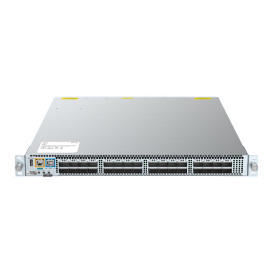
Page 11: Appearance
Hardware Installation and Reference Guide Overview Cooling system: provides five fan module slots and supports 4+1 fan redundancy. 1.3.1 Appearance 1. Appearance Figure 1-1 Front View of Front-to-Rear Airflow Figure 1-2 Rear View of Front-to-Rear Airflow... - Page 12 Hardware Installation and Reference Guide Overview Figure 1-3 Front View of Rear-to-Front Airflow Figure 1-4 Rear View of Rear-to-Front Airflow 2. Structure Figure 1-5 Front Panel Structure...
- Page 13 Hardware Installation and Reference Guide Overview Table 1-3 Front Panel Components Component USB 2.0 port Console port Management port QSFP28 port LED QSFP28 port System status LED Power status LED Fan status LED Asset tag Figure 1-6 Rear Panel Structure Table 1-4 Rear Panel Components Component...
-
Page 14: Leds
Hardware Installation and Reference Guide Overview 1.3.2 LEDs Table 1-5 LEDs Silkscreen Description Label Solid green: The system is operating normally. Blinking green: The system is starting up. Solid yellow: System ○ The system (including all modules) is not functioning properly. status LED ○... -
Page 15: Ports
Hardware Installation and Reference Guide Overview 1.3.3 Ports Table 1-6 Ports Port Connector Type Description Accessory The 100GE QSFP28 port can be split into four 25GE ports or two 50GE ports. It is backward compatible with 40GE and can be 40GE optical module Subject to the optical split into four 10GE ports for... - Page 16 Hardware Installation and Reference Guide Overview Rear-to-front: Air flows in through the power module and out through the ports, as shown in Figure 1-8. Caution Maintain a minimum clearance of 200 mm (7.87 in.) around the equipment for air circulation. ...
-
Page 17: Technical Specifications
Hardware Installation and Reference Guide Overview Figure 1-8 Rear-to-Front Airflow 1.3.5 Technical Specifications Table 1-7 Technical Specifications Class Item Specification 2.2 GHz quad-core Memory 4 GB, DDR4 SODIMM (up to two SODIMM with 32 GB) Technical indicators Flash memory NOR flash: MB (for BootROM) 240 GB Without packing materials: 442 mm x 560 mm x 44 mm (17.40... - Page 18 Hardware Installation and Reference Guide Overview Class Item Specification 32 x 100GE QSFP28 ports Service port Backward compatible with 40GE, split into four 10GE ports One 100GE port split into four 25GE ports or two 50GE ports Ports 32 x 100GE QSFP28 ports Service port Backward compatible with 40GE, split into four 10GE ports One 100GE port split into four 25GE ports or two 50GE ports...
- Page 19 Hardware Installation and Reference Guide Overview Class Item Specification PA550II-F: ○ Rated voltage: 110 V AC/220 V AC ○ Rated voltage range: 100 V AC to 120 V AC/ 200 V AC to 240 V AC (50 Hz to 60 Hz) ○...
-
Page 20: Asset Tag
Figure 1-9 Asset Tag Power Modules The smart power modules for the M2-S6510-32C support power consumption management and hot swapping. They can obtain the output power, output current, and operating temperature in real time. Caution ... -
Page 21: Pa550Ii-F
Hardware Installation and Reference Guide Overview 1.4.1 PA550II-F 1. Appearance Figure 1-10 Appearance Figure 1-11 Structure Table 1-8 Components Component Description Handle Handle of the power module Forward fan (front-to-rear airflow) Power connector C14 three-pin connector Power status LED Latch Latch of the power module... - Page 22 Hardware Installation and Reference Guide Overview 2. LED Table 1-9 Silkscreen Description Label Solid green: The power module is outputting power normally. Blinking green at 1 Hz: ○ The power module is in PS OFF state with only 12 V standby output. ○...
-
Page 23: Pa550Ii-R
Hardware Installation and Reference Guide Overview Item Specification Over-temperature protection Supported 1.4.2 PA550II-R Appearance Figure 1-12 Appearance Figure 1-13 Structure Table 1-11 Components Component Description Handle Handle of the power module... - Page 24 Hardware Installation and Reference Guide Overview Reverse fan Power connector Three-pin connector Power status LED Latch Latch of the power module Table 1-12 Silkscreen Description Label Solid green: The power module is outputting power normally. Blinking green at 1 Hz: ○...
-
Page 25: Fan Modules
Hardware Installation and Reference Guide Overview Power connector C14 connector for connection with AC power cord Rated input voltage range 100 V AC to 240 V AC, 50 Hz to 60 Hz Max. input voltage range 90 V AC to 264 V AC, 47 Hz to 63 Hz Rated. - Page 26 Hardware Installation and Reference Guide Overview Figure 1-15 Structure Table 1-14 Components Component Description Handle Handle of the fan module Fan status LED Latch Latch of the fan module 2. LED Table 1-15 Silkscreen Description Label Solid green: The fan module is operating normally. Fan status Blinking green: The fan module is being initialized.
-
Page 27: M1Hfan Iii-R
Hardware Installation and Reference Guide Overview Item Specification Weight Without packing materials: 0.39 kg (0.86 lbs.) Number of fans Rated voltage 12 V DC Max. power consumption 38.4 W Max. fan rotation speed 24,000 RPM Max. airflow volume 36 CFM Max. - Page 28 Hardware Installation and Reference Guide Overview Figure 1-17 Structure Table 1-17 Components Component Description Handle Handle of the fan module Fan status LED Latch Latch of the fan module Table 1-18 Silkscreen Description Label Solid green: The fan module is operating normally. Fan status Blinking green: The fan module is being initialized.
-
Page 29: Cables
Hardware Installation and Reference Guide Overview Item Specification Weight Without packing materials: 0.39 kg (0.86 lbs.) Number of fans Rated voltage 12 V DC Max. power consumption 33.12 W Max. fan rotation speed 22,500 RPM Max. airflow volume 37.89 CFM Max. -
Page 30: Ethernet Cable
2. AC Power Cord Select AC power cords based on the types of power sockets used in your equipment room. Micas provides the following types of power cords to suit different the power sockets: ... -
Page 31: Grounding Wire
Hardware Installation and Reference Guide Preparing for Installation Figure 1-19 AC Power Cord Structure 1.6.4 Grounding Wire Figure 1-20 Grounding Wire Table 1-22 Grounding Wire Components Component Description Cable sleeve UL1015 12 AWG, yellow-green, 3 meters (9.84 ft.), crimping RNB 5.5-8 lug Copper washer ID: 6.4 mm (0.25 in.), OD: 11.5 mm (0.45 in.), T: 1 mm (0.04 in.) Preparing for Installation... -
Page 32: General Precautions
Hardware Installation and Reference Guide Preparing for Installation 2.1.1 General Precautions Install the equipment in a standard 19-inch EIA rack. Keep the chassis clear and dust free. Avoid liquid inside the equipment. Keep the equipment far away from heat sources. ... -
Page 33: Preventing Esd Damage
Hardware Installation and Reference Guide Preparing for Installation 2.1.4 Preventing ESD Damage Static electricity comes from two major sources: Outdoor high-voltage power cords, lightning, and other external electric fields Indoor flooring materials and equipment enclosure When the static electricity exceeds a certain value, it will damage the circuit and equipment. To prevent ESD damage, attention should be paid to the following items: ... -
Page 34: Floor Loading
Hardware Installation and Reference Guide Preparing for Installation 2.2.1 Floor Loading Ensure that the floor under the rack supporting the chassis is capable of supporting the combined weight of the rack and all the other components. 2.2.2 Airflow To ensure adequate airflow through the chassis, maintain a minimum clearance of 20 cm (7.87 in.) around air vents. -
Page 35: Cleanliness
Hardware Installation and Reference Guide Preparing for Installation 2.2.6 Cleanliness The indoor dust takes on a positive or negative static electric charge when falling on the switch, causing poor contact of the metallic joint. Such electrostatic adhesion may occur more easily when the relative humidity is low, not only affecting the service life of the switch, but also causing communication faults. -
Page 36: Preventing Electromagnetic Interference
Hardware Installation and Reference Guide Preparing for Installation Ensure that the rack and power distribution system are securely grounded. Otherwise, electric shocks may occur when the insulation resistance between the power module and the chassis becomes small. Caution The building should provide a protective ground connection to ensure that the equipment is connected to a protective earth. -
Page 37: Surge Protection
Hardware Installation and Reference Guide Preparing for Installation Take electromagnetic shielding measures when necessary. 2.2.9 Surge Protection Although the equipment can guard against lightning strikes, strong lightning strikes may still damage the equipment. Take the following surge protection measures: ... -
Page 38: Tools
Hardware Installation and Reference Guide Preparing for Installation Tools Table 2-3 Tools Tools Description Common tools Philips screwdriver, utility knife, adjustable wrench, ESD-preventive clothing ESD-preventive wrist strap, ESD-preventive glove, marker, cage nuts, screws, Dedicated tools cables, and cable ties Note The tool kit does not come with the equipment. - Page 39 Hardware Installation and Reference Guide Preparing for Installation Figure 2-3 (2) Use a paper cutter to cut the tapes holding the cardboard sleeves of the box, and open the shipping box. Figure 2-4 Take out the accessory box, verify that the main accessories are not missing, and then keep the accessory box handy.
-
Page 40: Installing The Switch
Hardware Installation and Reference Guide Installing the Switch Figure 2-6 Place the switch with the panel foam facing upwards. Remove the panel foam and set it aside. Move the switch with both hands onto the shipping box of another product, and remove the foam on the other side. -
Page 41: Installation Procedure
Hardware Installation and Reference Guide Installing the Switch Installation Procedure Figure 3-1 Installation Procedure Start Prepare Install the chassis. Connect the grounding wire. Install the power module. Connect the power cord. Verify installation. Set the power Troubleshoot switch to ON. Set the power Normal? switch to OFF. -
Page 42: Installing The Rack
Hardware Installation and Reference Guide Installing the Switch Verifying Installation Connecting the Power Installing the Rack 3.2.1 Installation Guidelines Make sure the following guidelines are met: All expansion bolts for securing the rack base to the ground are installed from bottom to up in the sequence of large flat washer, spring washer, and nut, and the installation holes on the base are flush with the expansion bolts. -
Page 43: Mounting The Chassis On The Rack
Hardware Installation and Reference Guide Installing the Switch door. As a result, the front door cannot be closed after Ethernet cables and optical fibers are connected to the chassis. Generally, maintain a minimum clearance of 10 mm (0.39 in.) between the front panel and the front door. -
Page 44: Mounting The Chassis On The Workbench
Hardware Installation and Reference Guide Installing the Switch (3) Slide the switch into the rack: Slide the rack-mount guides onto the guide rails, and then gently slide the switch all the way into the rack. (4) Secure the switch to the rack: Secure the switch to the rack posts using the quick-release thumb screws. Caution ... -
Page 45: Installing And Removing The Fan Module
Hardware Installation and Reference Guide Installing the Switch (2) Crimp one end of the grounding wire to the grounding terminal of the chassis and the other end to the grounding terminal of the rack or the grounding bar of the equipment room. Danger ●... -
Page 46: Removing The Fan Module
Hardware Installation and Reference Guide Installing the Switch 3.5.2 Removing the Fan Module (1) Grasp the handle on the fan module and slide the module out of the slot. (2) Install the filler panel in the empty slot. Put the removed module back into its packing materials. Figure 3-5 Removing the Fan Module Warning... -
Page 47: Removing The Power Module
Hardware Installation and Reference Guide Installing the Switch Figure 3-6 Installing the PA550II-F Warning Slide the power module all the way into the chassis gently. Align the power module in the right orientation to the open power slot. If you are not able to push the power module all the way into the slot, carefully slide the module out of the slot, align the module with guide rails, and reinstall the module. -
Page 48: Installing And Removing The Pluggable Module
Installing and Removing the Pluggable Module Note Make sure that you have mounted the chassis on the rack before installing the pluggable module. For procedure. Please access Micas Networks at https://www.Micasnetworks.com/ for details. Verifying Installation Caution Before verifying installation, make sure that all power supplies are turned off. -
Page 49: Connecting The Power Cord
Hardware Installation and Reference Guide Commissioning Connecting the Power Cord Connect the power cord according to the notation on the power module and location requirements. Take the AC power cord as an example: (1) Connect one end of the AC power cord to the power connector. (2) Connect the other end of the AC power cord to the power socket of the external power system. - Page 50 Hardware Installation and Reference Guide Commissioning Click Serial in the left column. Set Bits per second to 115,200, Data bits to 8, Parity to None, Stop bits to 1, and Flow control to None. Click Open to set up the connection.
-
Page 51: Powering On The Device
Hardware Installation and Reference Guide Commissioning (4) After setting up the configuration environment, power on the device. If the device is already configured with a password, a notification will appear. Click Accept, and enter your username and password for connection. Powering on the Device 4.2.1 Checklist Before Power-on... -
Page 52: Monitoring And Maintenance
Hardware Installation and Reference Guide Monitoring and Maintenance Monitoring and Maintenance Monitoring 5.1.1 Monitoring the LEDs Each module installed in the chassis features a LED, which can be used to monitor the status of each module while the switch is running. See 1 Overview for details. -
Page 53: Replacing The Fan Module
5.2.4 Replacing the Fuse To replace the fuse, please contact your distributor or technical support team. Table 5-2 Fuse Specifications Product ID Chassis Fuse Bits Specifications M2-S6510-32C-FA 5 A/125 V M2-S6510-32C M2-S6510-32C-RA F 5A/125V... -
Page 54: Troubleshooting
Hardware Installation and Reference Guide Troubleshooting Troubleshooting Flowchart The equipment is not working properly. Check whether the rack is installed properly. Check whether the chassis is mounted on the rack properly. Check whether the power cord is connected properly. Check whether the power module is installed properly. -
Page 55: Common Issues
Hardware Installation and Reference Guide Troubleshooting Common Issues 6.2.1 Forgetting Login Password Symptom The login password is forgotten. Handling Method Contact technical support team. 6.2.2 AC Power Module Failure Symptom All LEDs on the front panel are off. The fan status LED is off, and the fan does not rotate. Handling Method Unplug the power cord from the power module. -
Page 56: Optical Port Linkdown
Hardware Installation and Reference Guide Appendix 6.2.6 Optical Port Linkdown Symptom The system runs normally. After you insert an optical transceiver into an optical port and plug in an optical cable, the link cannot be set up. Handling Method Check whether the receive and transmit ends are reversed. The transmit end of an optical port must be connected to the receive end of the peer port. -
Page 57: Label Contents
Hardware Installation and Reference Guide Appendix Figure 7-1 Keeping the Label Text Area Facing Right or Downwards (2) Labeling procedure Figure 7-2 Signal Cable Labeling Procedure 7.1.3 Label Contents The contents of the two sides of the label identify the location of the ports connected to the two ends of the power cord. -
Page 58: Connectors And Media
Hardware Installation and Reference Guide Appendix Figure 7-3 Signal Cable Label Connectors and Media 7.2.1 1000BASE-T Port Compliant with the IEEE 802.3ab standard, 1000BASE-T requires CAT5, CAT5e or higher standard 100-ohm twisted pairs with a distance of up to 100 meters (328.08 ft.). The 1000BASE-T port employs four pairs of wires for data transmission. -
Page 59: 100Base-Tx/10Base-T Port
Hardware Installation and Reference Guide Appendix MDI Mode MDI-X Mode Media Dependent Interface D+ Media Dependent Interface C+ Media Dependent Interface D– Media Dependent Interface C– The 1000BASE-T port employs all four pairs of wires for data transmission. Figure 7-5 shows the twisted pair connection for the 1000BASE-T port. -
Page 60: Surge Protection
Hardware Installation and Reference Guide Appendix Figure 7-6 100BASE-TX/10BASE-T Twisted Pairs Surge Protection 7.3.1 Installing an AC Power Arrester When an AC power cord from outdoors is directly plugged into the power port of the switch, the AC power connector must be connected to an external surge protector power strip to protect the switch against lightning strikes. -
Page 61: Installing An Ethernet Port Arrester
Hardware Installation and Reference Guide Appendix Note The power arrester does not come with the equipment. Please purchase it based on actual requirements. Important points: Make sure that the PE terminal of the power arrester is well grounded. After the AC power plug of the switch is connected to the socket of the power arrester (surge protector power strip), the surge protection function is implemented only if the LED indicating operation status is green and the LED indicating alarm status is OFF. -
Page 62: Site Selection
Hardware Installation and Reference Guide Appendix Figure 7-8 Installing an Ethernet Port Arrester Note The Ethernet port arrester is only for the 10/100 Mbps electrical ports with an RJ-45 connector. The Ethernet port arrester is not delivered with the switch. Please purchase it as required. The Ethernet port arrester user manual contains technical parameters and maintenance and installation instructions for the Ethernet port arrester. -
Page 63: Recommended Cabling
Hardware Installation and Reference Guide Appendix heavy rain as well as away from dust. If the dust is unavoidable, keep the door and window away from the pollution source. The equipment room should be away from the residential area. Otherwise, the equipment room should meet the construction standard in terms of noise. - Page 64 Hardware Installation and Reference Guide Appendix than the diameter of the optical cable. ○ During cabling, the bend radius of the optical cable should be over 10 times greater than the diameter of the optical cable. Precautions for Bundling up Cables ○...
- Page 65 Hardware Installation and Reference Guide Appendix Figure 7-10 Bundling Up Cables (2) When cables need to be bent, please bundle them up but do not tie them where the cables will be bent, as shown in Figure 7-11. Figure 7-11 Bundling Up Cables (3) ...
- Page 66 Hardware Installation and Reference Guide Appendix Figure 7-12 Cable Fastening Hard power cords should be fastened in the terminal connection area to prevent stress on terminal connection and cable. Do not use self-tapping screws to fasten terminals. Power cords of the same type and in the same cabling orientation should be bundled up into one cable bundle.
Need help?
Do you have a question about the M2-S6510-32C and is the answer not in the manual?
Questions and answers