Table of Contents
Advertisement
Quick Links
Advertisement
Table of Contents

Related Manuals for THORLABS LP126MU


Summary of Contents for THORLABS LP126MU
- Page 1 LP126MU(/M) and LP126CU(/M) Low-Profile Scientific Digital Cameras User Guide...
-
Page 2: Table Of Contents
Re-Assembly of the Window, C-Mount Adapter, and Flange Focus Adjustment ..........11 3.7.1 I/O Port Descriptions ............................12 3.7.2 Auxiliary Cable ..............................12 Chapter 4 Operation ......................... 13 4.2.1 Camera-Specific Timing Considerations ......................15 Chapter 5 LP126MU(/M) Specifications ..................17... - Page 3 Chapter 6 LP126CU(/M) Specifications ..................19 Chapter 7 Protective Glass Windows ..................21 Chapter 8 Mechanical Drawings ....................23 Chapter 9 Troubleshooting ....................... 24 Chapter 10 Maintenance ......................27 Chapter 11 Regulatory ........................ 29 Chapter 12 Warranty ........................32...
- Page 4 Low-Profile Scientific Digital Cameras Chapter 13 Thorlabs Worldwide Contacts ................... 33...
-
Page 5: Chapter 1 Safety
Any modification or servicing of this system by unqualified personnel renders Thorlabs free of any liability. This device can only be returned when packed into the complete original packaging, including all foam packing inserts. If necessary, ask for replacement packaging. -
Page 6: Service
Although the camera is easily adapted for custom interfaces, to achieve the listed specifications, this camera should only be used with accessories provided by Thorlabs. Any modification or servicing by unqualified personnel renders the warranty null and void, leaving Thorlabs free of liability. Please contact Thorlabs for questions on customization. -
Page 7: Chapter 2 Introduction
“xx” is the multiplier and “y” is the exponent of 10, M/C denotes monochrome or color, and U indicates a USB 3.0 interface. Using the LP126MU as an example, the 126 indicates the camera has 12 x 10 pixels (12 megapixels), is monochrome, and has a USB 3.0 interface. - Page 8 Lens Cap 3 x CA3339 MMCX-to-BNC Signal Cable Included Software Thorlabs Camera Software and SDK Available for Download from www.thorlabs.com/software All cameras are supplied with one USB 3.0 cable. These cables are constructed to provide reliable data throughput at a length of 3 m.
-
Page 9: Chapter 3 Setup And Installation
Select the driver that matches the interface on your camera, in this case USB3.0. Thorlabs offers various cameras with Gigabit Ethernet or Camera Link interfaces. If you have more than one camera, and they have different interfaces, select all that apply. - Page 10 Once a driver is selected, the red X will be replaced with a hard drive icon as shown in the USB selection below. Note: Thorlabs no longer sells Camera Link models, but the software still supports them. If you are upgrading your software and have Camera Link cameras, please select the driver during the previous step.
- Page 11 Once setup is complete, you may now proceed to the next section that will describe how to connect and power on your camera. When the camera is connected and powered up, you can navigate to the ThorCam Imaging Software as shown below: “Start” → “All Programs” → “Thorlabs” → “ThorCam” Rev. A, September 26, 2023 Page 7...
-
Page 12: Installing 3 Rd Party Software Application Support
3.2.4 Installing 3 Party Software Application Support After installation of Thorlabs components is completed, you have access to interfaces for select 3 -party image analysis packages you may already have installed on your computer, such as MATLAB®. -party application software interfaces are located in Zip files in the following directory:... -
Page 13: Using A C-Mount Lens
For the best results, the use of a C-mount lens that matches the optical format of the sensor’s imaging area is recommended (refer to the sensor specifications starting at Chapter 5). For more information on Thorlabs C- Mount lenses, please visit https://www.thorlabs.com. -
Page 14: Using The Camera With A Cage System
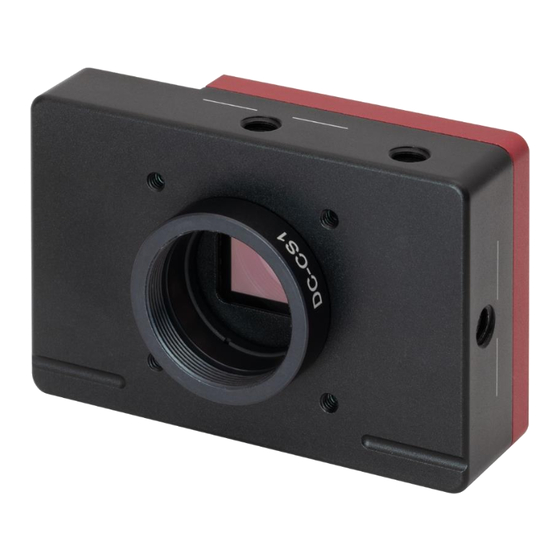
Chapter 3: Setup and Installation 3.4.3 Using the Camera with a Cage System The cameras have four 4-40 tapped holes for compatibility with Thorlabs’ 30 mm Cage systems. For mor information on Thorlabs’ 30 mm Cage system components, please visit www.thorlabs.com. 3.4.4 SM1 Compatible Threads The included DC-CS1 C-mount adapter (1.000”-32) can be completely removed (See Figure 3), exposing internal... -
Page 15: Window Removal And Replacement Procedure
Window Removal and Replacement Procedure Thorlabs Low-profile Scientific cameras are provided with a protective glass window installed (See Section 3.5.1). Note: If no glass is installed, dust and debris may collect on the sensor faceplate. Care must be taken when cleaning a sensor faceplate to avoid damage to the sensor. -
Page 16: I/O Port Descriptions
FVAL UT (Output): FVAL OUT refers to the “Frame Valid Output” and is an LVTTL output that is High during active readout lines. FVAL_OUT remains High throughout the active readout and returns Low between frames. 3.7.2 Auxiliary Cable Three Thorlabs CA3339 BNC-to-MMCX 1 m long cables are supplied with each camera. Page 12 ITN005664-D02... -
Page 17: Chapter 4 Operation
If you are using the ThorCam Image Acquisition Software please refer to the ThorCam User Guide, which can be accessed in the Documentation selection under the Start menu / All Programs listing for Thorlabs’ products. Rev. A, September 26, 2023... - Page 18 Compact Scientific Digital Cameras Chapter 4: Operation Camera Timing Diagrams Figure 4 Timing Diagram - Standard, Frames per Trigger = 0 or > 1 Figure 5 Timing Diagram - Standard, Frames per Trigger = 1 Page 14 ITN005664-D02...
-
Page 19: Camera-Specific Timing Considerations
Low-Profile Scientific Digital Cameras Chapter 4: Operation Figure 6 Timing Diagram - Bulb Mode 4.2.1 Camera-Specific Timing Considerations Due to the general operation of our Kiralux CMOS sensor cameras, as well as typical system propagation delays, the timing relationships shown above are subject to the following considerations: 1. - Page 20 Please refer to the ThorCam User Guide for more details, which can be accessed in the Documentation selection under the Start menu / All Programs listing for Thorlabs’ products. Note: If the Frame-Rate Control feature is not visible when operating your Kiralux Low-profile camera, please visit https://www.thorlabs.com/software_pages/ViewSoftwarePage.cfm?Code=ThorCam...
-
Page 21: Chapter 5 Lp126Mu(/M) Specifications
Low-Profile Scientific Digital Cameras Chapter 5: LP126MU(/M) Specifications Chapter 5 LP126MU(/M) Specifications CMOS Sensor Specifications Sensor Specifications CMOS Monochrome Sensor Type 4096 (H) x 3000 (V) (∼12.3 MP) Number of Active Pixels 3.45 µm x 3.45 µm Pixel Size 1.1” Format Optical Format (14131 µm x 10350 µm) - Page 22 Compact Scientific Digital Cameras Chapter 5: LP126MU(/M) Specifications Imaging Specifications Imaging Specifications Exposure Time 0.028 to 14700.9 ms ADC Resolution 12 Bits Vertical and Horizontal Digital Binning 1 x 1 to 16 x 16 Region of Interest (Width x Height)
-
Page 23: Chapter 6 Lp126Cu(/M) Specifications
Low-Profile Scientific Digital Cameras Chapter 6: LP126CU(/M) Specifications Chapter 6 LP126CU(/M) Specifications CMOS Sensor Specifications Sensor Specifications CMOS Color Sensor Type 4096 (H) x 3000 (V) (∼12.3 MP) Number of Active Pixels 3.45 µm x 3.45 µm Pixel Size 1.1” Format Optical Format (14131 µm x 10350 µm) Up to 71 dB... - Page 24 Compact Scientific Digital Cameras Chapter 6: LP126CU(/M) Specifications Imaging Specifications Imaging Specifications Exposure Time 0.028 to 14700.9 ms ADC Resolution 12 Bits Vertical and Horizontal Digital Binning 1 x 1 to 16 x 16 Region of Interest (Width x Height) 260 x 4 Pixels to 4096 x 3000 Pixels Read Noise <2.5 e...
-
Page 25: Chapter 7 Protective Glass Windows
Low-Profile Scientific Digital Cameras Chapter 7: Protective Glass Windows Chapter 7 Protective Glass Windows The protective glass window may be either an AR (anti-reflective) coated window for monochrome cameras, or an IR filter for color cameras. Protective Glass Window Dimensions Figure 7 Protective Window Dimensions AR-Coated Window Specifications... - Page 26 Compact Scientific Digital Cameras Chapter 7: Protective Glass Windows IR Filter Transmission Curve Figure 8 IR Blocking Filter Transmission Curve Page 22 ITN005664-D02...
-
Page 27: Chapter 8 Mechanical Drawings
Low-Profile Scientific Digital Cameras Chapter 8: Mechanical Drawings Chapter 8 Mechanical Drawings Figure 9 Dimensions for Low-Profile Scientific Camera Series Rev. A, September 26, 2023 Page 23... -
Page 28: Chapter 9 Troubleshooting
Compact Scientific Digital Cameras Chapter 9: Troubleshooting Chapter 9 Troubleshooting Interface Problem Symptoms Possible Cause Remedy Connect Camera to USB No Power to Camera 3.0 Port Restart / Refresh software after the • Software Does The camera has yet to camera has been Not Display a complete “enumeration”. - Page 29 Camera is not “armed” See Section 4.1 and “started” properly. Use a PCIe high bandwidth USB 3.0 Card, such as: Thorlabs’ USB3- PCIE. Low Bandwidth USB 3.0 Port Use a Different USB 3.0 • Excessive port, preferably one...
- Page 30 Compact Scientific Digital Cameras Chapter 9: Troubleshooting Software Problem Symptoms Possible Cause Remedy Make sure the camera is Power Not On connected to the USB 3.0 Port. • Error message, Make sure the camera is or camera does Not Plugged In connected to the USB 3.0 not show up in Camera Not Found...
-
Page 31: Chapter 10 Maintenance
For an informative tutorial refer to the Handling and Cleaning Procedures for Optical Components. The following guidelines, specific to Thorlabs’ cameras, are meant to be used in conjunction with the procedures described in the tutorial. - Page 32 5. Re-examine once again and repeat the process once, if necessary. If contamination continues to be a problem, please call Thorlabs for assistance. Caution Ethyl and isopropyl alcohols are highly flammable! Do not use near extreme heat, arcing electrical equipment (such as space heaters) or open flame! Use only with the proper ventilation.
-
Page 33: Chapter 11 Regulatory
Waste Treatment is Your Own Responsibility If you do not return an “end of life” unit to Thorlabs, you must hand it to a company specialized in waste recovery. Do not dispose of the unit in a litter bin or at a public waste disposal site. - Page 34 Compact Scientific Digital Cameras Chapter 11: Regulatory Certifications and Compliance – CE Declaration of Conformity Page 30 ITN005664-D02...
- Page 35 However, there is no guarantee that interference will not occur in a particular installation. Thorlabs is not responsible for any radio television interference caused by modifications of this equipment or the substitution or attachment of connecting cables and equipment other than those specified by Thorlabs.
-
Page 36: Chapter 12 Warranty
Chapter 12 Warranty General Product Warranty Thorlabs warrants that all products sold will be free from defects in material and workmanship and will conform to the published specifications under normal use, when correctly installed and maintained. Specific Warranties and Repairs All specific warranty and repair information can be found in the general terms and conditions located at https://www.thorlabs.com/Images/PDF/LG-PO-001_Thorlabs_terms_and_%20agreements.pdf. - Page 37 Low-Profile Scientific Digital Cameras Chapter 13: Thorlabs Worldwide Contacts Chapter 13 Thorlabs Worldwide Contacts For technical support or sales inquiries, please visit us at for our most up-to-date www.thorlabs.com/contact contact information. USA, Canada, and South America UK and Ireland Thorlabs, Inc.
- Page 38 www.thorlabs.com...
Need help?
Do you have a question about the LP126MU and is the answer not in the manual?
Questions and answers