
Related Manuals for Star Lake AV800-D27-A45S4


Summary of Contents for Star Lake AV800-D27-A45S4
- Page 1 AV800-D27-A45S4 IP65 MILTARY ICELAKE D-2796NT, 10GSFP, 10G Base-T, with GPU server User’s Manual User’s Manual Revision Date: Jul. 25. 2023...
-
Page 2: Safety Information
AV800-D27-A45S4 User’s Manual Revision Date: Jul. 25. 2023 Safety Information Electrical safety To prevent electrical shock hazard, disconnect the power cable from the electrical outlet before relocating the system. When adding or removing devices to or from the system, ensure that the power cables for the devices are unplugged before the signal cables are connected. -
Page 3: Revision History
2023/07/25 Initial release Version 2.0 2023/09/18 Update RS232/422/485 pin define Packing list □ AV800-D27-A45S4 Rugged GPU server System □ CD (Driver + Quick Installation Guide) Ordering Information Model Number Description AV800_D27-A45S4 Rugged military GPU server with Intel® Xeon® Ice Lake-D D‐2796NT processor, Nvidia MXM GPU Quadro RTX A4500, 18~36V DC‐IN, Operating... -
Page 4: Table Of Contents
AV800-D27-A45S4 User’s Manual Revision Date: Jul. 25. 2023 Table of contents Safety Information ..............................1 Electrical safety ..............................1 Operation safety ..............................1 Statement .................................1 Revision History..............................2 Packing list ................................2 Ordering Information ............................2 Chapter 1: Product Introduction ..........................5 Key Features ............................5 1.2 Mechanical Dimensions ..........................8 1.3 Front I/O ..............................9... - Page 5 AV800-D27-A45S4 User’s Manual Revision Date: Jul. 25. 2023 Appendix-C ................................ 63 Appendix-D ................................ 64...
-
Page 6: Chapter 1: Product Introduction
AV800-D27-A45S4 User’s Manual Revision Date: Jul. 25. 2023 Chapter 1: Product Introduction 1-1 Key Features System High Performance Intel® Xeon® Processor D-2796NT (Frequency 2.0GHz, Turbo Boost Frequency up to Processor 3.1GHz), 20-Core, 40 Thread Support, 30MB SmartCache. Turbo Boost Technology 2.0, Hyper-Threading support. - Page 7 AV800-D27-A45S4 User’s Manual Revision Date: Jul. 25. 2023 1x GbE TVS07RF-11-35S-LC connector 1x USB3.0 USB3FTV7AZNF312 connector 1x VGA D-sub 15 connector with waterproof cap Side I/O Button 1 x Power Switch with Dedicated LED SSD Tray 2 x Dual 2.5" U.2/SSD Easy Swap Tray...
- Page 8 AV800-D27-A45S4 User’s Manual Revision Date: Jul. 25. 2023 Method 500.5, Procedures III and IV (Altitude, Non-Operation): 15,240, (50,000 ft) for the initial cabin altitude (14.9Kpa or 2.16 Psia) Method 501.5, Procedure I (Storage/High Temperature) Method 501.5, Procedure II (Operation/High Temperature) Method 502.5, Procedure I (Storage/Low Temperature)
-
Page 9: Mechanical Dimensions
AV800-D27-A45S4 User’s Manual Revision Date: Jul. 25. 2023 1.2 Mechanical Dimensions... -
Page 10: Front I/O
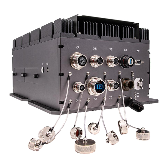
AV800-D27-A45S4 User’s Manual Revision Date: Jul. 25. 2023 1.3 Front I/O 1 x CAN BUS (D38999) TVS07RF-9-98S 1x10GbE(SFP+) (D38999) LCFTV70GN 1 x 10GbE (D38999) TVS07RF-11-35S 1x DC-IN (D38999 ) TVS07RF-13-4P 4 x RS232/422/485(D38999) 24FD35SNDC-IN 1 x GbE (D38999) TVS07RF-11-35S 1 x GbE (D3899) TVS07RF-11-35S 1 x USB3.0 (D38999) -
Page 11: Chapter 2: Jumpers And Connectors Locations
AV800-D27-A45S4 User’s Manual Revision Date: Jul. 25. 2023 Chapter 2: Jumpers and Connectors Locations 2.1 Front Bezel Connector Pin Definitions X1: 1 x CAN BUS CAN BUS PIN DEFINE AMPHENOL TVS07RF-9-98S CAN-L CAN-H X2: 1x10GbE(SFP+) – AMPHENOL LCFTV70GN X3: 1 x 10GbE... - Page 12 AV800-D27-A45S4 User’s Manual Revision Date: Jul. 25. 2023 X4: 1x DC-IN DC-IN PIN DEFINE AMPHENOL TV07RW-13-4P Vin + Vin + Vin - Vin - X5: 4 x RS232/422/485 AMPHENOL TVS07RF-15-35S PIN DEFINE PIN DEFINE RS232 RS422 RS485 RS232 RS422 RS485...
- Page 13 AV800-D27-A45S4 User’s Manual Revision Date: Jul. 25. 2023 X6 & X7: 1 x GbE PIN DEFINE AMPHENOL TV07RW-11-35SN TP1+ WHITE / ORANGE TP1- ORANG TP2+ WHITE / GREEN TP3- BLUE TP3+ WHITE / BLUE TP2- GREEN TP4+ WHITE / BROWN...
-
Page 14: Power Button, Led & Hdd Led
AV800-D27-A45S4 User’s Manual Revision Date: Jul. 25. 2023 2.2 Power Button, LED & HDD LED The Power Button connection is located on pins 1 and 2 of JF1. Momentarily contacting both pins will power on/off the system. This button can also be configured to function as a suspend button (with a setting in the BIOS - see Chapter 4). -
Page 15: Chapter 3 Uefi Bios
AV800-D27-A45S4 User’s Manual Revision Date: Jul. 25. 2023 Chapter 3 UEFI BIOS Introduction This chapter describes the AMIBIOS™ Setup utility for the motherboard. The BIOS is stored on a chip and can be easily upgraded using a flash program. Note: Due to periodic changes to the BIOS, some settings may have been added or deleted and might not yet be recorded in this manual. -
Page 16: Main Setup
AV800-D27-A45S4 User’s Manual Revision Date: Jul. 25. 2023 Main Setup When you first enter the AMI BIOS setup utility, you will enter the Main setup screen. You can always return to the Main setup screen by selecting the Main tab on the top of the screen. -
Page 17: Advanced
AV800-D27-A45S4 User’s Manual Revision Date: Jul. 25. 2023 3-3 Advanced Use the arrow keys to select the Advanced menu and press <Enter> to access the menu features. Warning: Take caution when changing the Advanced settings. An incorrect value, a very high DRAM frequency, or an incorrect DRAM timing setting may make the system unstable. - Page 18 AV800-D27-A45S4 User’s Manual Revision Date: Jul. 25. 2023 Power Configuration Watch Dog Function If enabled, the Watch Dog Timer allows the system to reset or generate NMI based on jumper settings when it is expired for more than five minutes. The options are Disabled and Enabled.
- Page 19 AV800-D27-A45S4 User’s Manual Revision Date: Jul. 25. 2023 CPU1 Core Disable Bitmap CPU1 Core Disable Bitmap Available Bitmap CPU Core Count CPU1 Cores Enable Select 0 to enable all cores or 17592186044415 (maximum) to disable all cores. One core must be enabled.
- Page 20 AV800-D27-A45S4 User’s Manual Revision Date: Jul. 25. 2023 PPIN Control Select Unlock/Enable to use the Protected Processor Inventory Number (PPIN) in the system. The options are Lock/Disable and Unlock/Enable. AES-NI Select Enable to use the Intel Advanced Encryption Standard (AES) New Instructions (NI) to ensure data security.
- Page 21 AV800-D27-A45S4 User’s Manual Revision Date: Jul. 25. 2023 Manager is responsible for coordinating the P-state, and must initiate the transition on all Logical Processors. The options are HW_ALL and SW_ALL. Turbo Mode This feature enables dynamic control of the processor, allowing it to run above stock frequency.
- Page 22 AV800-D27-A45S4 User’s Manual Revision Date: Jul. 25. 2023 Software Controlled T-States Use this feature to enable Software Controlled T-States. The options are Disable and Enable. If the feature above is set to Enable, the next feature is available for configuration: T-State Throttle Level Use this feature to enable or disable CPU throttling, which reduces power consumption.
- Page 23 AV800-D27-A45S4 User’s Manual Revision Date: Jul. 25. 2023 Enforce POR Select POR (Plan of Record) to enforce POR restrictions on DDR4 frequency and voltage programming. The options are POR and Disable. PPR Type Use this feature to select the Post Package Repair (PPR) type. The options are PPR Disabled, Hard PPR, and Soft PPR.
- Page 24 AV800-D27-A45S4 User’s Manual Revision Date: Jul. 25. 2023 source). When this item is set to Enable, the IO hub reads and writes back one cache line every 16K cycles if there is no delay caused by internal processing. By using this method, roughly 64 GB of memory behind the IO hub is scrubbed every day.
- Page 25 AV800-D27-A45S4 User’s Manual Revision Date: Jul. 25. 2023 Select Yes to use Intel Virtualization Technology for Direct I/O VT-d support by reporting the I/O device assignments to the Virtual Machine Monitor (VMM) through the DMAR ACPI tables. This feature offers fully-protected I/O resource sharing across Intel platforms, providing greater reliability, security and availability in networking and data-sharing.
- Page 26 AV800-D27-A45S4 User’s Manual Revision Date: Jul. 25. 2023 JSLIM1 PCIe 4.0 X8 VMD Port0 / JSLIM1 PCIe 4.0 X8 VMD Port1 / JSLIM2 PCIe 4.0 X8 VMD Port0 / JSLIM2 PCIe 4.0 X8 VMD Port1 Use this feature to enable or disable the volume management device for this expansion slot. The options are Disable and Enable.
- Page 27 AV800-D27-A45S4 User’s Manual Revision Date: Jul. 25. 2023 Support Aggressive Link Power Management When this feature is set to Enable, the SATA AHCI controller manages the power usage of the SATA link. The controller puts the link in a low power mode during extended periods of I/O inactivity and then returns the link to an active state when I/O activity resumes.
- Page 28 AV800-D27-A45S4 User’s Manual Revision Date: Jul. 25. 2023 SATA Port 0/1/4/5/6/7 Spin Up Device Set this feature to enable or disable the PCH to initialize the device. The options are Disabled and Enabled. SATA Port 0/1/4/5/6/7 SATA Device Type Use this feature to specify if the SATA port specified should be connected to a Solid State Drive or a Hard Disk Drive.
- Page 29 AV800-D27-A45S4 User’s Manual Revision Date: Jul. 25. 2023 Interface Type MAC Address Host addresses Route Table Gateway addresses DNS addresses Interface ID Use this feature to set the 64-bit alternative interface ID for the device. DAD Transmit Count If this set feature is set to 0, the Duplication Address Detection is not performed. Set the value to a preferred selection.
- Page 30 AV800-D27-A45S4 User’s Manual Revision Date: Jul. 25. 2023 Maximum Read Request Use this item to select the Maximum Read Request size of the PCIe device, or select Auto to allow the System BIOS to determine the value. The options are Auto, 128 Bytes, 256 Bytes, 512 Bytes, 1024 Bytes, 2048 Bytes, and 4096 Bytes.
- Page 31 AV800-D27-A45S4 User’s Manual Revision Date: Jul. 25. 2023 Device Settings This feature displays the status of the serial port. Change Settings This feature specifies the base I/O port address and the Interrupt Request address of the serial port. Select Auto to allow the BIOS to automatically assign the base I/O and IRQ address. The options are Auto, (IO=3F8h;...
- Page 32 AV800-D27-A45S4 User’s Manual Revision Date: Jul. 25. 2023 19200, 38400, 57600 and 115200 (bits per second). Data Bits Use this feature to set the data transmission size for Console Redirection. The options are 7 Bits and 8 Bits. Parity A parity bit can be sent along with regular data bits to detect data transmission errors. Select Even if the parity bit is set to 0, and the number of 1's in data bits is even.
- Page 33 AV800-D27-A45S4 User’s Manual Revision Date: Jul. 25. 2023 Select Enabled to use the SOL port for Console Redirection. The options are Disabled and Enabled. *If the feature above is set to Enabled, the following features are available for configuration: ...
- Page 34 AV800-D27-A45S4 User’s Manual Revision Date: Jul. 25. 2023 Recorder Mode Select Enabled to capture the data displayed on a terminal and send it as text messages to a remote server. The options are Disabled and Enabled. Resolution 100x31 Select Enabled for extended-terminal resolution support. The options are Disabled and Enabled.
- Page 35 AV800-D27-A45S4 User’s Manual Revision Date: Jul. 25. 2023 57600, and 115200 (bits per second). Flow Control EMS Use this item to set the flow control for Console Redirection to prevent data loss caused by buffer overflow. Send a "Stop" signal to stop sending data when the receiving buffer is full.
- Page 36 AV800-D27-A45S4 User’s Manual Revision Date: Jul. 25. 2023 Enable. Active PCR Bank Available PCR banks SHA-1 PCR Bank Use this feature to disable or enable the SHA-1 Platform Configuration Register (PCR) bank for the installed TPM device. The options are Disabled and Enabled.
- Page 37 AV800-D27-A45S4 User’s Manual Revision Date: Jul. 25. 2023 Use this feature to select whether HTTPS Boot checks the hostname of TLS certificates matches the hostname provided by the remote server. The options are Enabled and Disabled (WARNING: Security Risk!). Priority of HTTP Boot: Instance of Priority 1: Use this feature to set the rank target port.
- Page 38 AV800-D27-A45S4 User’s Manual Revision Date: Jul. 25. 2023 CA Certificate Use this feature to enroll factory defaults or load the CA certificates from a file. The options are Update, Delete, and Export. Client Certificate Use this feature to enroll factory defaults or load the client certificates from a file. The options are Update, Delete, and Export.
- Page 39 AV800-D27-A45S4 User’s Manual Revision Date: Jul. 25. 2023 NIC Configuration Legacy Boot Protocol Use this feature to select a non-UEFI boot protocol. The options are None, PXE, iSCSI Primary, and iSCSI Secondary. Link Speed Wake On LAN Select Enabled for wake on LAN support, which allows the system to wake up when an onboard LAN device receives an incoming signal.
- Page 40 AV800-D27-A45S4 User’s Manual Revision Date: Jul. 25. 2023 Use this feature to input the certification GUID. Commit Changes and Exit Use this feature to save all changes and exit TLS settings. Discard Changes and Exit Use this feature to discard all changes and exit TLS settings.
- Page 41 AV800-D27-A45S4 User’s Manual Revision Date: Jul. 25. 2023 RAID Volumes: This feature displays the information of RAID volumes have been created earlier. Intel(R) VROC sSATA Controller Note 1: This feature is based on your system and related device(s) installed.
- Page 42 AV800-D27-A45S4 User’s Manual Revision Date: Jul. 25. 2023 Root Port Number Root Port Offset Slot Number Socket Number VMD Controller Number PCI Bus:Device.Function VMD Bus:Device.Function Port 4:2, Slot 0, CPU0, VMD4, BDF 03:00.0 INTEL SSDPE2KE016T8 SN:PHLN928100J11P6AGN, 1490, 42GB INTEL SSDPE2KE016T8 SN:PHLN928100J11P6AGN, 1490, 42GB...
- Page 43 AV800-D27-A45S4 User’s Manual Revision Date: Jul. 25. 2023 Use this feature to select the RAID Level. The default option is RAID0(Stripe). Enable RAID Spanned over VMD Controllers Use this feature to enable RAID Spanned over VMD controllers. Select Disks: INTEL SSDPE2KE016T8 SN:PHLN928100J11P6AGN, 1490, 42GB Port 4:2 CPU0 VMD4 Select X to select the disk.
- Page 44 AV800-D27-A45S4 User’s Manual Revision Date: Jul. 25. 2023 Model Number Serial Number Size Status Block Size Root Port Number Root Port Offset Slot Number Socket Number VMD Controller Number PCI Bus:Device.Function VMD Bus:Device.Function Port 4:2, Slot 0, CPU0, VMD4, BDF 03:00.0 ...
- Page 45 AV800-D27-A45S4 User’s Manual Revision Date: Jul. 25. 2023 Intel(R) VROC 7.7.0.1054 SATA Driver Intel(R) VROC 7.7.0.1054 sSATA Driver Intel(R) PRO/1000 9.3.10 PCIe Controller 5ED9D898 Child 0 Intel(R) I350 Gigabit Network Connection Intel(R) 10GbE Driver 7.9.05 x64...
-
Page 46: Bmc
AV800-D27-A45S4 User’s Manual Revision Date: Jul. 25. 2023 3-4 BMC Use this menu to configure BMC settings. BMC Firmware Revision This feature displays the IPMI firmware revision used in your system. IPMI STATUS (Baseboard Management Controller) This feature displays the status of the IPMI firmware installed in your system. - Page 47 AV800-D27-A45S4 User’s Manual Revision Date: Jul. 25. 2023 Note: All values changed here do not take effect until computer is restarted. BMC Network Configuration BMC Network Configuration Update IPMI LAN Configuration Select Yes for the BIOS to implement all IP/MAC address changes at the next system boot.
- Page 48 AV800-D27-A45S4 User’s Manual Revision Date: Jul. 25. 2023 Configuration Address Source This feature allows you to select the source of the IP address for this computer. If Static is selected, you need to know the IP address of this computer and enter it to the system manually in the field. If DHCP is selected, the BIOS searches for a Dynamic Host Configuration Protocol (DHCP) server in the network that is attached to and request the next available IP address for this computer.
-
Page 49: Event Logs
AV800-D27-A45S4 User’s Manual Revision Date: Jul. 25. 2023 3-5 Event Logs Use this menu to configure the following security settings for the system. Change SMBIOS Event Log Settings Enabling/Disabling Options SMBIOS Event Log Change this feature to enable or disable all features of the SMBIOS Event Logging during system boot. - Page 50 AV800-D27-A45S4 User’s Manual Revision Date: Jul. 25. 2023 This option toggles the System Boot Event logging to enabled or disabled. The options are Disabled and Enabled. MECI The Multiple Event Count Increment (MECI) counter counts the number of occurrences that a duplicate event must happen before the MECI counter is incremented.
-
Page 51: Security
AV800-D27-A45S4 User’s Manual Revision Date: Jul. 25. 2023 3-6 Security Use this menu to configure Security settings. Administrator Password Press Enter to create a new or change an existing Administrator password. Password Check Select Setup for the system to check for a password at Setup. Select Always for the system to check for a password at boot up or upon entering the BIOS Setup utility. - Page 52 AV800-D27-A45S4 User’s Manual Revision Date: Jul. 25. 2023 Security Erase - Without Password. HDD Name HDD Serial Number Security Mode Security Function Enable or Disable this feature to erase the device without a password. The options are Disable and Security Erase - Without Password.
- Page 53 AV800-D27-A45S4 User’s Manual Revision Date: Jul. 25. 2023 Remove 'UEFI CA' from DB Restore DB defaults Select Yes to restore the DB defaults. Secure Boot Variable Platform Key (PK) Update Select Yes to load a factory default PK or No to load from a file on an external media.
-
Page 54: Boot
AV800-D27-A45S4 User’s Manual Revision Date: Jul. 25. 2023 3-7 Boot Use this menu to configure Boot settings. Boot Configuration FIXED BOOT ORDER Priorities • Boot Option #1 • Boot Option #2 • Boot Option #3 • Boot Option #4 • Boot Option #5 •... - Page 55 AV800-D27-A45S4 User’s Manual Revision Date: Jul. 25. 2023 Path for boot option Use this feature to enter the path to the boot option. Boot option File Path Create Use this feature to create the newly formed boot option. Delete Boot Option This feature allows you to select a boot device to delete from the boot priority list.
-
Page 56: Save & Exit
AV800-D27-A45S4 User’s Manual Revision Date: Jul. 25. 2023 3-8 Save & Exit Use this menu to save settings and exit from the BIOS. Save Options Discard Changes and Exit Select this option to quit the BIOS Setup without making any permanent changes to the system configuration, and reboot the computer. - Page 57 AV800-D27-A45S4 User’s Manual Revision Date: Jul. 25. 2023 To set this feature, select Restore Defaults from the Save & Exit menu and press <Enter>. These are factory settings designed for maximum system stability, but not for maximum performance. Save As User Defaults To set this feature, select Save as User Defaults from the Save &...
- Page 58 AV800-D27-A45S4 User’s Manual Revision Date: Jul. 25. 2023 Appendix-A Appendix A BIOS Codes A.1 BIOS Error POST (Beep) Codes During the Power-On Self-Test (POST) routines, which are performed each time the system is powered on, errors may occur. Non-fatal errors are those which, in most cases, allow the system to continue the boot up process.
- Page 59 AV800-D27-A45S4 User’s Manual Revision Date: Jul. 25. 2023 Appendix-B Appendix B Software After the hardware has been installed, you can install the Operating System (OS), configure RAID settings and install the drivers. B.1 Microsoft Windows OS Installation If you will be using RAID, you must configure RAID settings before installing the Windows OS and the RAID driver.
- Page 60 AV800-D27-A45S4 User’s Manual Revision Date: Jul. 25. 2023 4.During Windows Setup, continue to the dialog where you select the drives on which to install Windows. If the disk you want to use is not listed, click on “Load driver” link at the bottom left corner.
- Page 61 AV800-D27-A45S4 User’s Manual Revision Date: Jul. 25. 2023 B.2 Driver Installation The Supermicro website that contains drivers and utilities for your system is at https://www. supermicro.com/wdl/driver/. Some of these must be installed, such as the chipset driver. After accessing the website, go into the CDR_Images (in the parent directory of the above link) and locate the ISO file for your motherboard.
- Page 62 AV800-D27-A45S4 User’s Manual Revision Date: Jul. 25. 2023 B.3 SuperDoctor® 5 The Supermicro SuperDoctor 5 is a program that functions in a command-line or web-based interface for Windows and Linux operating systems. The program monitors such system health information as CPU temperature, system voltages, system power consumption, fan speed, and provides alerts via email or Simple Network Management Protocol (SNMP).
- Page 63 AV800-D27-A45S4 User’s Manual Revision Date: Jul. 25. 2023 B.4 IPMI The 10th Generation Intel Xeon, Core™ i3, Pentium, Celeron supports the Intelligent Platform Management Interface (IPMI). IPMI is used to provide remote access, monitoring and management. There are several BIOS settings that are related to IPMI.
- Page 64 AV800-D27-A45S4 User’s Manual Revision Date: Jul. 25. 2023 Appendix-C Appendix C Standardized Warning Statements The following statements are industry standard warnings, provided to warn the user of situations which have the potential for bodily injury. Should you have questions or experience difficulty, contact Supermicro's Technical Support department for assistance.
- Page 65 AV800-D27-A45S4 User’s Manual Revision Date: Jul. 25. 2023 Appendix-D Appendix D UEFI BIOS Recovery Warning: Do not upgrade the BIOS unless your system has a BIOS-related issue. Flashing the wrong BIOS can cause irreparable damage to the system. In no event shall Supermicro be liable for direct, indirect, special, incidental, or consequential damages arising from a BIOS update.
- Page 66 AV800-D27-A45S4 User’s Manual Revision Date: Jul. 25. 2023 D.3 Recovering the BIOS Block with a USB Device This feature allows the user to recover the main BIOS image using a USB-attached device without additional utilities used. A USB flash device such as a USB Flash or media drive can be used for this purpose.
- Page 67 AV800-D27-A45S4 User’s Manual Revision Date: Jul. 25. 2023 Note 2: Before recovering the main BIOS image, confirm that the "Super.ROM" binary image file you download is the same version or a close version meant for your motherboard. 2. Insert the USB device that contains the new BIOS image ("Super.ROM") into your USB port and reset the system until the following screen appears: 3.
- Page 68 AV800-D27-A45S4 User’s Manual Revision Date: Jul. 25. 2023 4.When the screen as shown above displays, use the arrow keys to select the item "Proceed with flash update" and press the <Enter> key. You will see the BIOS recovery progress as shown in the screen below: Note: Do not interrupt the BIOS flashing process until it has completed.
- Page 69 AV800-D27-A45S4 User’s Manual Revision Date: Jul. 25. 2023 8. When the UEFI Shell prompt appears, type fs# to change the device directory path. Go to the directory that contains the BIOS package you extracted earlier from Step 6. Enter flash.nsh BIOSname.### at the prompt to start the BIOS update process.
Need help?
Do you have a question about the AV800-D27-A45S4 and is the answer not in the manual?
Questions and answers