
Related Manuals for simatherm simatec IH 045


Summary of Contents for simatherm simatec IH 045
- Page 1 Induction Heater IH 045 Bedienungsanleitung Instructions for use Mode d‘emploi Manuale d‘istruzioni Manual de instrucciones...
- Page 2 Induktions-Anwärmgerät IH 045 © simatec ag...
- Page 3 Deutsch English Français Italiano Español © simatec ag Induktions-Anwärmgerät IH 045...
-
Page 4: Table Of Contents
Inhaltsverzeichnis EU-Konformitätserklärung Bluetooth Modul Zertifizierung Sicherheitshinweise Einführung Zweckbestimmung Funktionsprinzip Herausragendes Merkmal Technische Beschreibung Bestandteile Technische Daten Vorbereitung der Inbetriebnahme Betrieb Funktion der Displays Funktion der Schalttasten 4.3.1 Temperaturmodus mit einer Sonde Temperaturmodus mit einer Sonde 4.3.2 Temperaturmodus mit einer Sonde emperaturmodus mit einer Sonde 4.3.3 Zeitmodus Temperaturmessung... -
Page 5: Eu-Konformitätserklärung
Stadthof 2 CH-3380 Wangen a. Aare erklärt, dass das Induktionsheizgerät simatherm IH 025 / 045 / 070 / 090 / 210 konstruiert und hergestellt wurden in Übereinstimmung mit der Richtlinie 2014/35/EU des europäischen Parlaments und des Rates zur Harmonisierung der Rechtsvorschriften der Mitgliedstaaten über die Bereit-... -
Page 6: Bluetooth Modul Zertifizierung
IH 045 contains Certified Bluetooth Modul FANSTEL BT832-F: • Europe: Certified • Australia: Certified • Japan TELEC: 201-180944 • QDID: 97989 • IC (Industrial Canada) ID: 4100A-BT832 • FCC ID: X8WBT832 / FRN: 0031152804 / Grantee Code: 2A2MP This device complies with part 15 of the FCC Rules. - Page 7 Sicherheitshinweis Um den Anwender und das simatherm Induktions-Anwärmgerät zu schützen, sind folgende Sicherheitshinweise zu befolgen: Verboten für Personen mit Herzschrittmachern oder anderen empfindlichen Implantaten. Das Tragen von Metallteilen, Uhren und Schmuck ist verboten. Warnung vor heißen Oberflächen. Warnung vor Magnetfeldern.
-
Page 8: Einführung
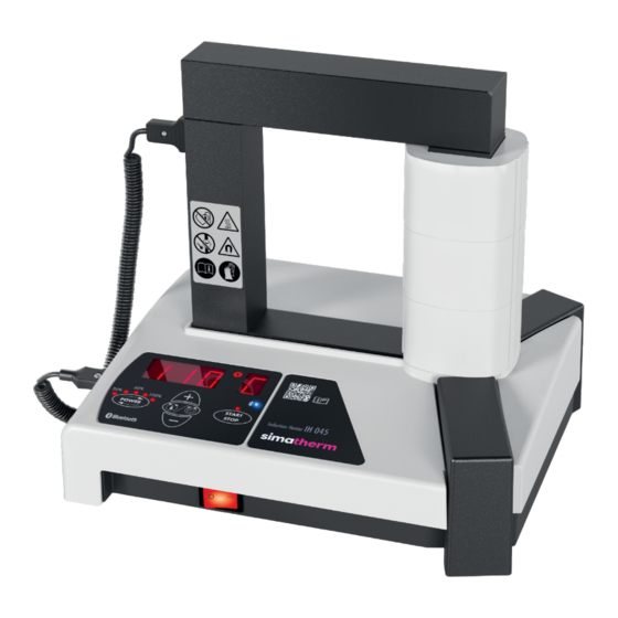
Einführung Das simatherm IH 045 Induktions-Anwärmgerät ist für die Erhitzung von Lagern oder anderen metallischen, ringförmigen Werkstücken gebaut. Die Wärme führt zu einer Ausdehnung des Werkstückes, so dass während der Montage auf das Gegenteil keine Kraft erforderlich ist. Bei der Erwärmung von Lagern reicht für die mühelose Montage ein Temperaturunterschied... -
Page 9: Herausragendes Merkmal
Herausragendes Merkmal Das simatherm IH 045 ist das weltweit erste Induktions-Anwärmgerät das via Bluetooth eine Verbindung mit dem Mobiltelefon ermöglicht. Dies garantiert für den Anwender eine schnelle, intuitive Bedienung mit direkter Kommu- nikation über die App für Support, Updates oder die Vorteile der digitalen Bedienerführung. -
Page 10: Technische Daten
Technische Daten IH 045 Bezeichnung IH 045 /230 V (Art. 110-12040) IH 045 /120 V (Art. 110-12050) IH 045 /100 V (Art. 110-12060) Empfohlener Stromkreisschutz 100/120 V: 16A-Sicherung 230 V: 10A-Sicherung Leistung 2,1 kVA 1,8 kVA 1,5 kVA Temperatursteuerung 20-180°C in 1°-Schritten Maximale Sonden-Temperatur 180°C Zeit-Modus... -
Page 11: Vorbereitung Der Inbetriebnahme
Vorbereitung der Inbetriebnahme Das Gerät horizontal auf eine stabile Abstellfläche stellen. WICHTIG: Prüfen Sie anhand des Typenschilds, ob das Gerät für die entspre- chende Spannung ausgelegt ist. Netzstecker an Stromquelle anschliessen und Hauptschalter betätigen. Achtung: Ohne ein korrekt positioniertes Joch darf der Anwärmprozess nicht gestartet werden. - Page 12 Können die Werkstücke um die vertikale Spule gelegt werden, ist immer das grösste Auflagejoch zu verwenden. Der optimale Wirkungsgrad wird nur bei der Verwendung des grösstmöglichen Joches erreicht. Werden die Werkstücke über dem Horizontaljoch erwärmt, ist darauf zu achten, dass immer das Joch mit grösst möglichem Querschnitt verwendet wird.
- Page 13 Bei Verwendung des TEMPERATUR-MODUS, die Temperatursonde(n) in die Buchse links am Heizgerät stecken. Das magnetische Ende der Sonde auf den inneren Ring des Lagers oder auf die innerste Stelle des Bauteils setzen. Im Betrieb mit Zwei-Sonden ist eine Sonde am Innenring, und die andere Sonde am Aussenring des Lagers oder Werkstückes zu platzieren.
- Page 14 ACHTUNG: Heisse Oberfläche. Tragen Sie die mitgelie- ferten Schutzhandschuhe für die Entnahme des heissen Lagers. Joche auf der Rückseite des Gerätes verstauen. Wichtig: Gerät keiner hoher Luftfeuchtigkeit aussetzen. Induktions-Anwärmgerät IH 045 © simatec ag...
-
Page 15: Betrieb
Betrieb Funktion der Displays A) Das Hauptdisplay zeigt die ausgewählte Heizzeit oder Heiztemperatur an. Display Anzeige Zeit in Minuten °C Temperatur in Grad Celsius °F Temperatur in Grad Fahrenheit °C Temperatursonde 1* °C Temperatursonde 2* * Es spielt keine Rolle in welcher Reihenfolge die Temperatursonden gesteckt werden. Die höhere Temperatur zeigt immer die Temperatur des Lagerinnenrings an. -
Page 16: Funktion Der Schalttasten
Funktion der Schalttasten Schalttaste Funktion POWER Anpassung der Leistung in 20%-Schritten. Die gewählte Leistung erscheint auf dem Leistungs-Display. POWER länger Die eingestellte Leistung wird halbiert, die LED‘s der Leistungs- als 5 s gedrückt anzeige blinken. Um die Halbierung rückgängig zu machen, halten drücken Sie die Taste POWER erneut 5 sek. -
Page 17: Temperaturmodus Mit Einer Sonde Temperaturmodus Mit Einer Sonde
4.3.1 Temperaturmodus mit der Sonde • Zeigt das Hauptdisplay “t”, auf MODE drücken, um in den TEMPERATUR- MODUS zu wechseln. Im TEMPERATURMODUS erscheint im Hauptdisplay °C oder °F. • Die gewählte Temperatur erscheint im Hauptdisplay. Die Voreinstellung für Lager ist 110°C. Wird eine andere Temperatur gewünscht, zur Anpas- sung der Temperatur in Schritten von 1°... -
Page 18: Temperaturmodus Mit Einer Sonde Emperaturmodus Mit Einer Sonde
4.3.2 Temperaturmodus mit zwei Sonden • Zeigt das Hauptdisplay “t”, auf MODE drücken, um in den TEMPERATUR- MODUS zu wechseln. Im TEMPERATURMODUS erscheint im Hauptdisplay °C oder °F. • Wird im TEMPERATURMODUS eine zweite Temperatursonde verwendet, wechselt das Gerät automatisch in den Delta-T Modus. •... -
Page 19: 4.3.3 Zeitmodus
4.3.3 Zeitmodus • Zeigt das Hauptdisplay °C oder °F, auf MODE drücken, um in den ZEIT- MODUS zu wechseln. Im ZEITMODUS erscheint auf dem Hauptdisplay „t“. • Zur Anpassung der Zeit in Schritten von 0,1 Minuten auf UP (Erhöhung) oder DOWN (Verringerung) drücken. •... -
Page 20: Wahl Der Leistungsstufe
Wahl der Leistungsstufe Bei der Erhitzung von Lagern mit einem Induktionsheizgerät wird ein Grossteil der Hitze im inneren Kugellagerring erzeugt. Anschliessend verteilt sich die Hitze über das Lager. Daher ist es wichtig, dass Lager mit kleinem Innenabstand oder leichter Vorbelastung langsam erhitzt werden. Dadurch wird sichergestellt, dass sich das Lager langsam ausdehnt und Schäden am Lager vermieden werden. -
Page 21: Störungssuche
Störungssuche Ein Systemfehler wird durch ein akustisches Signal und einen der folgenden Fehlercodes auf dem Hauptdisplay angezeigt: Display Fehler Massnahme E03 E Überhitzung der Spule Warten, bis die Induktionsspule abkühlt. E05 E Temperaturanstieg von Den Anschluss der Temperaturson- weniger als 1° alle 30 de überprüfen. -
Page 22: Simatec App World Of Maintenance
simatec App World of Maintenance Das simatec Gerät IH 045 kann auch via App WoM betrieben werden. App Downloaden und installieren, für den Betrieb den Anweisungen in der App folgen. Induktions-Anwärmgerät IH 045 © simatec ag... - Page 23 Table of contents EU Declaration of conformity UKCA Declaration of conformity Bluetooth module certification Safety recommendations Introduction Intended use Principle of operation Distinguishing feature Description Components Technical data Preparation for use Operation Function of displays Function of buttons 4.3.1 Temp mode with one probe Temp mode with one probe 4.3.2 Temp mode with two probes 4.3.3 Time Mode...
-
Page 24: Eu Declaration Of Conformity
EU Declaration of conformity simatec ag, Stadthof 2, CH-3380 Wangen a. Aare, Switzerland, declares that the Induction Heater simatherm IH 025 / 045 / 070 / 090 / 210 are designed and manufactured in accordance with Directive 2014/35/EU of the European Parliament and of the Council on the harmonisation... -
Page 25: Bluetooth Module Certification
IH 045 contains Certified Bluetooth Modul FANSTEL BT832-F: • Europe: Certified • Australia: Certified • Japan TELEC: 201-180944 • QDID: 97989 • IC (Industrial Canada) ID: 4100A-BT832 • FCC ID: X8WBT832 / FRN: 0031152804 / Grantee Code: 2A2MP This device complies with part 15 of the FCC Rules. - Page 26 Security note To protect the user and the simatherm induction heating device, the following safety instructions must be followed. Forbidden for persons with heart pacemaker or other sensitive implants. Wearing of metal parts, watches and jewellery forbidden. Warning of hot surface.
-
Page 27: Introduction
Introduction The simatec IH 045 induction heater is designed to heat bearings or other metallic, ring-shaped workpieces. The heat causes the bearing to expand, which eliminates the need to use force during installation. A 90°C (194°F) temperature difference between the bearing and shaft is generally sufficient to enable installation. -
Page 28: Distinguishing Feature
Distinguishing feature The simatherm IH 045 is the world’s first induction heating device to con- nect to a mobile phone via Bluetooth. This guarantees the user fast, intuitive operation with direct communication via the app for support, updates or the advantages of digital operator guidance. -
Page 29: Technical Data
Technical data IH 045 Designation IH 045 /230 V (Art. 110-12040) IH 045 /120 V (Art. 110-12050) IH 045 /100 V (Art. 110-12060) Recommended circuit protection 100/120 V: 16A circuit breaker 230 V: 10A circuit breaker Power 2,1 kVA 1,8 kVA 1,5 kVA Temperature control 20-180°C (68-356°F) in steps... -
Page 30: Preparation For Use
Preparation for use Place the device horizontally on a stable surface. IMPORTANT: Check the type plate to ensure that the appliance is designed for the appropriate voltage. Connect the mains plug to the power source and press the main switch Attention: Never operate the IH 045 without a yoke in position. - Page 31 If the workpieces can be placed around the vertical coil, always use the larg- est support yoke. The optimum efficiency is only achieved when using the largest possible yoke. If the workpieces are heated above the horizontal yoke, make sure that the yoke with the largest possible cross-section is always used. In order to be able to use the units optimally, three standard yokes are avail- able for all units.
- Page 32 If using TEMPERATURE MODE, insert the temperature probe(s) into the socket on the left of the heater. Place the magnetic end of the probe on the inner ring of the bearing or on the innermost part of the component. When operating with two probes, place one probe on the inner ring and the other probe on the outer ring of the bearing or workpiece.
- Page 33 ATTENTION: Hot surface. Always wear the protective gloves provided when removing the hot bearing. Stow the yokes on the back of the unit. Important: Avoid exposing the device to high humidity. © simatec ag Induction Heater IH 045...
-
Page 34: Operation
Operation Function of displays A) The main display shows the selected time or temperature for heating. Display Indication time in minutes °C temperature in degrees Celsius °F temperature in degrees Fahrenheit °C temperature probe 1* °C temperature probe 2* * It does not matter in which order the temperature probes are plugged in. The higher temperature always indicates the temperature of the bearing inner ring. -
Page 35: Function Of Buttons
Function of buttons Button Function POWER Press to adjust the power in steps of 20%. The selected power is indicated on the power display. Hold POWER for The LEDs of the power indicator flash when set power is halved. longer than 5s To cancel the power reduction, press the POWER button again and hold for 5 seconds. -
Page 36: Temp Mode With One Probe Temp Mode With One Probe
4.3.1 Temp mode with one probe • If the main display shows “t”, press MODE to select TEMP MODE. The main display shows °C or °F in TEMP MODE. • The selected temperature is shown on the main display. The default temperature for bearings is 110°C (230°F). -
Page 37: 4.3.2 Temp Mode With Two Probes
4.3.2 Temp mode with two probes • If the main display shows “t”, press MODE to select TEMP MODE. The main display shows °C or °F in TEMP MODE. • If a second temperature probe is used in TEMPERATURE MODE, the de- vice automatically switches to Delta-T mode. -
Page 38: 4.3.3 Time Mode
4.3.3 Time mode • If the main display shows °C or °F, press MODE to select TIME MODE. The main display shows “t” in TIME MODE. • Press UP or DOWN to adjust the time in steps of 0.1 minute. •... -
Page 39: Power Level Selection
Power level selection When heating bearings with an induction heater, most of the heat will be generated in the inner ring of the bearing. The heat will then be transferred through the bearing. It is therefore important that bearings with small internal clearance or slight preload are heated slowly. -
Page 40: Troubleshooting
Troubleshooting A system fault will be indicated by an acoustic signal and one of the follow- ing fault codes on the main display: Display Fault Action E03 E Overheated coil Wait until the inductive coil cools. E05 E Temperature increase of Check the temperature probe connec- less than 1°... -
Page 41: Simatec App World Of Maintenance
World of Maintenance The simatec IH 045 can also be operated via the WoM app. Download and install the app, follow the instructions in the app for operation. © simatec ag Induction Heater IH 045... - Page 42 Tabele des matières Déclaration UE de conformité Certification du module Bluetooth Recommandations de sécurité Indtroduction Utilisation prévue Principe de fonctionnement Fonction remarquable Description Composants Caractéristiques techniques Préparation avant l‘utilisation Utilisation Fonction des écrans Fonction des touches 4.3.1 Mode température avec une sonde 4.3.2 Mode température avec deux sondes 4.3.3 Mode „Durée“...
-
Page 43: Déclaration Ue De Conformité
Stadthof 2, CH-3380 Wangen a. Aare, Suisse confirme que le Chauffage par induction simatherm IH 025 / 045 / 070 / 090 / 210 est construit et fabriqué en concordance avec la Directive 2014/35/UE du Parlament Européen et du Conseil relative à... -
Page 44: Certification Du Module Bluetooth
IH 045 contains Certified Bluetooth Modul FANSTEL BT832-F: • Europe: Certified • Australia: Certified • Japan TELEC: 201-180944 • QDID: 97989 • IC (Industrial Canada) ID: 4100A-BT832 • FCC ID: X8WBT832 / FRN: 0031152804 / Grantee Code: 2A2MP This device complies with part 15 of the FCC Rules. - Page 45 Consignes de sécurité Afin de protéger l’utilisateur et l’appareil de chauffage par induction simatherm, les consignes de sécurité suivantes doivent être respectées: Interdit aux personnes portant un stimulateur cardiaque ou d’autres implants sensibles. Port de pièces métalliques, de montres et de bijoux sont interdits.
-
Page 46: Indtroduction
Introduction Le IH 045 est un appareil de chauffage par induction conçu pour chauffer les roulements et autres pièces métalliques de forme annulaire. La chaleur produite dilate le roulement, et permet ainsi d‘effectuer un montage „sans forcer“. Un écart de température de 90°C entre le roulement et l‘arbre est en général suffisant pour le montage. -
Page 47: Fonction Remarquable
Fonction remarquable Le simatherm IH 045 est le premier appareil de chauffage par induction au monde à se connecter à un téléphone portable via Bluetooth. Cela garantit à l’utilisateur une utilisation rapide et intuitive avec une communication directe via l’application pour l’assistance, les mises à jour ou les avantages du gui- dage numérique de l’opérateur. -
Page 48: Caractéristiques Techniques
Caractéristiques techniques IH 045 Dénomination IH 045 /230 V (Art. 110-12040) IH 045 /120 V (Art. 110-12050) IH 045 /100 V (Art. 110-12060) Protection du circuit recommandée 100/120 V: 16A Disjoncteur 230 V: 10A Disjoncteur Puissance 2,1 kVA 1,8 kVA 1,5 kVA Contrôle de température 0-180°C par paliers de 1°... -
Page 49: Préparation Avant L'utilisation
Préparation à l‘utilisation Placer l’appareil horizontalement sur une surface stable. IMPORTANT: Vérifiez la plaque signalétique pour vous assurer que l’appareil est conçu pour la tension appropriée. Branchez la fiche secteur sur la source d’alimentation et appuyez sur l’interrupteur principal. Attention: Ne jamais utiliser l‘IH 045 sans que barreau soit en position. - Page 50 Si les pièces peuvent être placées autour de la bobine, utilisez toujours bar- reau le plus grand. L’efficacité optimale n’est atteinte qu’en utilisant barreaux le plus grand possible. Si les pièces sont chauffées horizontalement, veillez à toujours utiliser le barreau avec la plus grande section possible. Afin de pou- voir utiliser les appareils de manière optimale, trois barreaux standard sont livrés.
- Page 51 Si vous utilisez le MODE TEMPERATURE, insérez la (les) sonde(s) de tempéra- ture dans la prise située à gauche de l’appareil de chauffage. Placez l’extré- mité magnétique de la sonde sur la bague intérieure du roulement ou sur la partie la plus intérieure du composant. Si vous utilisez deux sondes, placez une sonde sur la bague intérieure et l’autre sur la bague extérieure du roule- ment ou de la pièce.
- Page 52 ATTENTION : Surface chaude. Portez les gants de protec- tion fournis pour retirer le roulement. Ranger les barreaux à l’arrière de l’appareil. Important: Ne pas exposer l’appareil à une forte humidité. Chauffage par Induction IH 045 © simatec ag...
-
Page 53: Utilisation
Utilisation Fonction des écrans A) L‘écran principal indique la durée choisie ou la température de chauffage. Affichage Indication Durée en minutes °C Température en degrés Celsius °F Température en degrés Fahrenheit °C Sonde de température 1* °C Sonde de température 2* * L’ordre dans lequel les sondes de température sont connectées n’a aucune importance. -
Page 54: Fonction Des Touches
Fonction des boutons Bouton Fonction POWER Appuyez sur ce bouton pour régler la puissance par intervalles de 20%. La puissance sélectionnée est indiquée par les DEL. Maintenir La puissance réglée est divisée par deux, les LED de l‘affichage POWER pendant de la puissance clignotent. -
Page 55: 4.3.1 Mode Température Avec Une Sonde
4.3.1 Mode température avec une sonde • Si l‘écran principal indique “t“, appuyez sur MODE pour sélectionner le MODE TEMP. L‘écran principal indique °C ou °F en MODE TEMP. • La température sélectionnée est indiquée sur l‘écran principal. La tem- pérature par défaut pour chauffer des roulements est de 110°C. - Page 56 4.3.2 Mode température avec deux sondes • Si l’écran principal affiche “t“, appuyer sur MODE pour passer en MODE TEMPÉRATURE. En mode TEMPÉRATURE l’écran principal affiche °C ou °F. • Si une deuxième sonde de température est utilisée en MODE TEMPÉRA- TURE, l’appareil passe automatiquement en mode Delta T.
-
Page 57: Mode Température Avec Deux Sondes
4.3.3 Mode „Durée“ • Si l‘écran principal indique °C ou °F, appuyez sur MODE pour sélectionne le mode „TIME MODE“. L‘écran principal affiche “t“ en TIME MODE. • Appuyez sur UP (pour augmenter) ou sur DOWN (pour baisser) pour régler la durée par intervalles de 0,1 minute. •... -
Page 58: Sélection Du Niveau De Puissance
Sélection du niveau de puissance Lors du chauffage de roulements avec un appareil de chauffage par in- duction, la plus grande partie de la chaleur sera produite au niveau de la bague intérieure du roulement. La chaleur se transfert ensuite progressive- ment au roulement. -
Page 59: Messages D'erreur
Messages d‘erreur Une erreur du système sera indiquée par un signal sonore et l‘un des codes d‘erreur suivants s‘affichera automatiquement sur l‘écran principal: Affichage Erreur Action E03 E Surchauffe de la bobine Attendre que la bobine à induction refroidisse. E05 E Augmentation de tempé- Vérifier le branchement de la rature de moins de 1°C... -
Page 60: Pièces De Rechange
Pièces de rechange No. d‘art. Description 190-12240 Barreau 42,5 x 42,5 x 219mm (pour roulements dont l’alésage mesure 60mm min.) 190-12230 Barreau 28 x 28 x 219mm (pour roulements dont l’alésage mesure 40mm min.) 190-12220 Barreau 14 x 14 x 219mm (pour roulements dont l’alésage mesure 20mm min.) 190-12260 Kit de support de pièce... -
Page 61: Simatec App World Of Maintenance
World of Maintenance L’appareil simatec IH 045 peut également être utilisé via l’app WoM. Télé- charger et installer l’app, suivre les instructions de l’app pour le fonctionne- ment. © simatec ag Chauffage par Induction IH 045... - Page 62 Indice Dichiarazione di conformità UE Certificazione del modulo bluetooth Norme di sicurezza Introduzione Uso previsto Principio di funzionamento Caratteristica esclusiva Descrizione Componenti Dati tecnici Preliminari all‘uso Funzionamento Funzione dello schermo Funzione dei pulsanti Temp Mode (Modalità Temperatura) 1 Sonda Temp Mode (Modalità Temperatura) 1 Sonda Temp Mode (Modalità...
-
Page 63: Dichiarazione Di Conformità Ue
Stadthof 2, CH-3380 Wangen a. Aare, Svizzera dichiara che il Riscaldatore a Induzione simatherm IH 025 / 045 / 070 / 090 / 210 è stato progettato e realizzato in conformità di: Direttiva 2014/35/UE del Parlamento europeo e del Consiglio concernente l’armonizzazione delle legislazioni degli Stati membri relative alla messa a... -
Page 64: Certificazione Del Modulo Bluetooth
IH 045 contains Certified Bluetooth Modul FANSTEL BT832-F: • Europe: Certified • Australia: Certified • Japan TELEC: 201-180944 • QDID: 97989 • IC (Industrial Canada) ID: 4100A-BT832 • FCC ID: X8WBT832 / FRN: 0031152804 / Grantee Code: 2A2MP This device complies with part 15 of the FCC Rules. - Page 65 Nota di sicurezza Per proteggere l’utente e il dispositivo di riscaldamento a induzione sima- therm, è necessario seguire le seguenti istruzioni di sicurezza: Vietato alle persone con pacemaker cardiaci o altri impianti sensibili. È vietato indossare parti metalliche, orologi e gioielli. Avviso di superficie calda Attenzione ai campi magnetici.
-
Page 66: Introduzione
Introduzione Il riscaldatore a induzione simatherm IH 045 è stato messo a punto per riscaldare i cuscinetti che devono essere montati con interferenza sull’albero. Durante l‘installazione non è necessario ricorrere alla forza perché il calore determina la dilatazione del cuscinetto. Di solito una differenza di temperatu- ra di 90°C tra l’anello interno del cuscinetto e l‘albero è... -
Page 67: Caratteristica Esclusiva
Caratteristica esclusiva Il simatherm IH 045 è il primo riscaldatore a induzione al mondo che si collega a un telefono cellulare tramite Bluetooth. Ciò garantisce all‘utente un funzionamento rapido e intuitivo con comunicazione diretta tramite l‘app per assistenza, aggiornamenti o i vantaggi della guida digitale dell‘operatore. -
Page 68: Dati Tecnici
Dati tecnici IH 045 Denominazione IH 045/230 V (Art. 110-12040) IH 045 /120 V (Art. 110-12050) IH 045 /100 V (Art. 110-12060) Protezione di circuito suggerita 100/120 V: Interruttore da 16A 230 V: Interruttore da 10A Potenza 2,1 kVA 1,8 kVA 1,5 kVA Controllo della temperatura 20-180°C con incrementi di 1°... -
Page 69: Preliminari All'uso
Preparazione all‘uso Posizionare l’apparecchio in orizzontale su una superficie stabile. IMPORTANTE: controllare la targhetta di identificazione per assicurarsi che l’apparecchio sia progettato per la tensione appropriata. Collegare la spina di rete alla fonte di alimentazione e azionare l’interruttore principale. Attenzione: non avviare il processo di riscaldamento senza un giogo posizionato correttamente. - Page 70 Se i pezzi possono essere posizionati intorno alla bobina verticale, utilizzare sempre il giogo di supporto più grande. L’efficienza ottimale si ottiene solo utilizzando il giogo più grande possibile. Se i pezzi vengono riscaldati sopra il giogo orizzontale, assicurarsi di utilizzare sempre il giogo con la sezione più...
- Page 71 Se si utilizza la MODALITÀ TEMPERATURA, inserire la o le sonde di tempera- tura nella presa a sinistra del riscaldatore. Posizionare l’estremità magnetica della sonda sull’anello interno del cuscinetto o sulla parte più interna del componente. Quando si opera con due sonde, posizionare una sonda sull’a- nello interno e l’altra sull’anello esterno del cuscinetto o del pezzo.
- Page 72 ATTENZIONE: Superficie calda. Indossare i guanti di pro- tezione in dotazione per rimuovere il cuscinetto caldo. Riporre i gioghi sul retro dell’apparecchio. Importante: Non esporre l’apparecchio a un’elevata umidità. Riscaldatore a Induzione IH 045 © simatec ag...
-
Page 73: Funzionamento
Funzionamento Funzione dello schermo A) Lo schermo principale visualizza la temperatura o il tempo di riscalda- mento selezionati. Schermo Indicazione Tempo in minuti °C Temperatura in gradi Celsius °F Temperatura in gradi Fahrenheit °C Sonda di temperatura 1* °C Sonda di temperatura 2* * Non importa l’ordine di inserimento delle sonde di temperatura. -
Page 74: Funzione Dei Pulsanti
Funzione dei pulsanti Pulsante Funzione POWER Premerlo per regolare la potenza dell‘alimentazione in incrementi del 20%. La potenza selezionata è visualizzata sullo schermo dell‘alimentazione. Per più di 5 s La potenza impostata viene dimezzata, i LED del display di tenere potenza lampeggiano. -
Page 75: 4.3.1 Temp Mode (Modalità Temperatura) 1 Sonda
4.3.1 Temp Mode (Modalità Temperatura) 1 Sonda • Se lo schermo principale visualizza “t“, premere MODE (MODALITÀ) per selezionare TEMP MODE (MODALITÀ TEMPERATURA). In TEMP MODE (MODALITÀ TEMPERATURA) lo schermo principale visualizza °C o °F. • La temperatura selezionata è visualizzata sullo schermo principale. La temperatura predefinita per i cuscinetti è... -
Page 76: 4.3.2 Temp Mode (Modalità Temperatura) 2 Sonde
4.3.2 Temp Mode (Modalità Temperatura) 2 Sonde • Quando il display principale visualizza “t“, premere MODE per passare alla MODALITÀ TEMPERATURA. In MODALITÀ TEMPERATURA il display principale visualizza °C o °F. • Se si utilizza una seconda sonda di temperatura in MODALITÀ TEMPERA- TURA, l‘unità... -
Page 77: Time Mode (Modalità Tempo)
4.3.3 Time Mode (Modalità Tempo) • Se lo schermo principale visualizza °C o °F, premere MODE (MODALITÀ) per selezionare TIME MODE (MODALITÀ TEMPO). Lo schermo principale visualizza “t“ in TIME MODE (MODALITÀ TEMPO). • Premere SU o GIÙ per regolare il tempo in incrementi di 0,1 minuti. •... -
Page 78: Selezione Del Livello Di Alimentazione
Selezione del livello di alimentazione Quando si riscaldano dei cuscinetti con un riscaldatore a induzione, la maggior parte del calore viene prodotta nella pista interna del cuscinetto. Il calore viene poi trasferito attraverso il cuscinetto. Ecco perché è importante che i cuscinetti con gioco interno piccolo o con un leggero precarico siano riscaldati lentamente. -
Page 79: Individuazione Guasti
Individuazione guasti Un guasto di sistema viene indicato da un segnale acustico e da uno dei seguenti codici di errore visualizzati sullo schermo principale: Schermo Guasto Azione E03 E Bobina surriscaldata Attendere che la bobina induttiva si raffreddi. E05 E Aumento di temperatura Controllare l‘attacco della sonda inferiore a 1°... -
Page 80: Ricambi
Ricambi No. articolo Descrizione 190-12240 Giogo 42,5 x 42,5 x 219mm (per cuscinetti con alesag- gio minimo di 60mm) 190-12230 Giogo 28 x 28 x 219mm (per cuscinetti con alesaggio minimo di 40mm 190-12220 Giogo 14 x 14 x 219mm (per cuscinetti con alesaggio minimo di 20mm) 190-12260 Set di supporti per IH 045... -
Page 81: Simatec App World Of Maintenance
APP World of Maintenance L’unità simatec IH 045 può essere comandata anche tramite l’app WoM. Scaricare e installare l’app, seguire le istruzioni per il funzionamento. © simatec ag Riscaldatore a Induzione IH 045... - Page 82 Índice Declaración UE de conformidad Certificación del módulo Bluetooth Recomendaciones de seguridad Introducción Uso previsto Principio de funcionamiento Características distintivas Descripción técnica Componentes Datos técnicos Preparación para su uso Funcionamiento Función de las pantallas Función de los botones 4.3.1 Modo de temperatura (TEMP MODE) 1 sonda Modo de temperatura (TEMP MODE) 1 sonda 4.3.2 Modo de temperatura (TEMP MODE) 2 sondas Modo de temperatura (TEMP MODE) 2 sondas...
-
Page 83: Declaración Ue De Conformidad
Stadthof 2, CH-3380 Wangen a. Aare, Suiza declaramos que el Calentador de Inducción simatherm IH 025 / 045 / 070 / 090 / 210 ha sido diseñado y fabricado de acuerdo con La Directiva 2014/35/UE del Parlamento Europeo y del Consejo sobre la armonización de las legislaciones de los Estados miembros en materia de... -
Page 84: Certificación Del Módulo Bluetooth
IH 045 contains Certified Bluetooth Modul FANSTEL BT832-F: • Europe: Certified • Australia: Certified • Japan TELEC: 201-180944 • QDID: 97989 • IC (Industrial Canada) ID: 4100A-BT832 • FCC ID: X8WBT832 / FRN: 0031152804 / Grantee Code: 2A2MP This device complies with part 15 of the FCC Rules. - Page 85 Advertencia de seguridad Para proteger al usuario y el dispositivo de calentamiento por inducción simatherm, deben seguirse las siguientes instrucciones de seguridad: Prohibido para personas con marcapasos cardíaco u otros implantes sensibles. Prohibido llevar piezas metálicas, relojes y joyas. Advertencia de superficie caliente.
-
Page 86: Introducción
Introduccion El calentador de inducción IH 045 ha sido diseñado para calentar roda- mientos instalados con ajuste de interferencia sobre un eje. El calor pro- voca la dilatación del rodamiento, lo que elimina la necesidad de utilizar la fuerza para su instalación. Normalmente basta con una diferencia de temperatura de 90°C entre el rodamiento y el eje para que sea posible la instalación. -
Page 87: Características Distintivas
Características distintivas simatherm IH 045 es la primera unidad de calentamiento por inducción del mundo que se conecta a un teléfono móvil a través de Bluetooth. Esto garantiza al usuario un funcionamiento rápido e intuitivo con comunicación directa a través de la aplicación para asistencia, actualizaciones o las ven- tajas de la guía digital del operador. -
Page 88: Datos Técnicos
Datos técnicos IH 045 Denominación IH 045 /230 V (Art. 110-12040) IH 045 /120 V (Art. 110-12050) IH 045 /100 V (Art. 110-12060) Protección de línea recomendada 100/120 V: Fusible de 16A 230 V: Fusible de 10A Tensión 2,1 kVA 1,8 kVA 1,5 kVA Modo de temperatura (TEMP MODE) -
Page 89: Preparación Para Su Uso
Preparación para su uso Coloque el aparato en posición horizontal sobre una superficie estable. IMPORTANTE: Compruebe la placa de características para asegurarse de que el aparato está diseñado para el voltaje adecuado. Conecte el enchufe a la toma de corriente y pulse el interruptor principal. Atención: El proceso de calentamiento no debe iniciarse sin un yugo correctamente colocado. - Page 90 Si las piezas pueden colocarse alrededor de la bobina vertical, utilice siem- pre el yugo de soporte más grande. La eficacia óptima sólo se consigue uti- lizando el yugo más grande posible. Si las piezas se calientan por encima del yugo horizontal, asegúrese de utilizar siempre el yugo con la sección transversal más grande posible.
- Page 91 Si utiliza el MODO TEMPERATURA, introduzca la(s) sonda(s) de temperatura en la toma situada a la izquierda del calefactor. Coloque el extremo magné- tico de la sonda en el anillo interior del rodamiento o en la parte más interna del componente. Si trabaja con dos sondas, coloque una en el anillo interior y la otra en el anillo exterior del rodamiento o de la pieza.
- Page 92 ATENCIÓN: Superficie caliente. Utilice los guantes de pro- tección suministrados para retirar el rodamiento caliente. Guarde los yugos en la parte posterior de la unidad. Importante: No exponga el aparato a una humedad elevada. Calentador de Inducción IH 045 © simatec ag...
-
Page 93: Funcionamiento
Funcionamiento Función de las pantallas A. La pantalla muestra el tiempo o la temperatura seleccionados para el calentamiento. Pantalla Indicación Tiempo en minutos °C Temperatura en grados Celsius °F Temperatura en grados Fahrenheit °C Sonda de temperatura 1* °C Sonda de temperatura 2* * Es indiferente el orden en que se enchufen las sondas de temperatura. -
Page 94: Función De Los Botones
Función de los botones Botón Función POWER Pulsa para ajustar la potencia. La potencia seleccionada aparece indicada con un LED. POTENCIA La potencia ajustada se reduce a la mitad, los LED de la pantalla durante más de de potencia parpadean. Para cancelar la reducción a la mitad 5 s mantenga pulse de nuevo el botón POWER durante 5 segundos. -
Page 95: Modo De Temperatura (Temp Mode) 1 Sonda Modo De Temperatura (Temp Mode) 1 Sonda
4.3.1 Modo de temperatura (TEMP MODE) 1 sonda • Si en la pantalla aparece “t”, pulse MODE para seleccionar TEMP MODE. La pantalla muestra °C o °F en TEMP MODE. • La temperatura seleccionada aparece indicada en la pantalla. La tempe- ratura predeterminada para los rodamientos es de 110ºC. -
Page 96: Modo De Temperatura (Temp Mode) 2 Sondas Modo De Temperatura (Temp Mode) 2 Sondas
4.3.2 Modo de temperatura (TEMP MODE) 2 sondas • Cuando la pantalla principal muestre “t”, pulse MODE para cambiar al MODO TEMPERATURA. En el MODO TEMPERATURA la pantalla principal muestra °C o °F. • Si se utiliza una segunda sonda de temperatura en el MODO TEMPERATU- RA, la unidad cambia automáticamente al modo Delta-T. -
Page 97: Modo De Tiempo (Time Mode)
4.3.3 Modo de tiempo (TIME MODE) • Si en la pantalla aparece °C o °F, pulse MODE para seleccionar TIME MODE. La pantalla muestra “t” en TIME MODE. • Pulse UP o DOWN para ajustar el tiempo en intervalos de 0,1 minutos. •... -
Page 98: Selección Del Nivel De Potencia
Selección del nivel de potencia Durante el calentamiento de rodamientos con un calentador de inducción, la mayor parte del calor se generará en el aro interior del rodamiento. El calor se transmitirá después a través del rodamiento. Por tanto, es importante calentar despacio los rodamientos con un juego interno reducido. -
Page 99: Resolución De Problemas
Resolución de problemas Los fallos del sistema se indicarán mediante una señal acústica y uno de los siguientes códigos de fallo en la pantalla de control remoto: Pantalla Fallo Acción E03 E Recalentamiento de la Espere a que la bobina de inducci- bobina ón se enfríe. -
Page 100: Piezas De Repuesto
Piezas de repuesto No. de articúlo Descripci ón 190-12240 Travesaño 42,5 x 42,5 x 219mm (para rodamientos con un diámetro interior de mínimo 60mm) 190-12230 Travesaño 28 x 28 x 219mm (para rodamientos con un diá- metro interior de mínimo 40mm) 190-12220 Travesaño 14 x 14 x 219mm (para rodamientos con un diá- metro interior de mínimo 20mm) -
Page 101: Simatec App World Of Maintenance
World of Maintenance The simatec IH 045 can also be operated via the WoM app. Download and install the app, follow the instructions in the app for operation. simatec ag Stadthof 2 3380 Wangen a. Aare Switzerland simatec.com...
Need help?
Do you have a question about the simatec IH 045 and is the answer not in the manual?
Questions and answers