
Subscribe to Our Youtube Channel
Related Manuals for ASRock Industrial N3160-NUC IPC


Summary of Contents for ASRock Industrial N3160-NUC IPC
- Page 1 N3160-NUC IPC User Manual Version 1.1 Updated May 2023 Copyright©2023 ASRockind INC. All rights reserved.
- Page 2 Version 1.0 Published November 2017 Copyright©2023 ASRockind INC. All rights reserved. Copyright Notice: No part of this documentation may be reproduced, transcribed, transmitted, or translated in any language, in any form or by any means, except duplication of documentation by the purchaser for backup purpose, without written consent of ASRockind Inc.
- Page 3 The terms HDMI and HDMI High-Definition Multimedia Interface, and the HDMI ® logo are trademarks or registered trademarks of HDMI Licensing LLC in the United States and other countries. CAUTION: RISK OF EXPLOSION IF BATTERY IS REPLACED BY AN INCORRECT TYPE. DISPOSE OF USED BATTERIES ACCORDING TO THE INSTRUCTIONS.
-
Page 4: Table Of Contents
Contents 1 Introduction ............5 1.1 Package Contents ............5 1.2 Specifications ..............6 1.3 Motherboard Layout ............8 1.4 I/O Panel ................ 10 2 Installation ............11 2.1 Screw Holes ..............11 2.2 Pre-installation Precautions ........... 11 2.3 Installation of Memory Modules (SO-DIMM) ....12 2.4 Expansion Slots ............ -
Page 5: Introduction
If you require technical support related to this motherboard, please visit our website for specific information about the model you are using. https://www.asrockind.com/support/index.asp 1.1 Package Contents ASRockind N3160-NUC IPC Motherboard (4.09” x 4.02” (104 x 102mm) ASRockind N3160-NUC IPC Jumper setting instruction... -
Page 6: Specifications
1.2 Specifications Form Dimensions 4.09" x 4.02" (104 x 102mm) Factor ® Intel Quad Core Braswell N3160 (With FAN) Supports Hyper-Threading Technology Core Processor Number System Max Speed (By CPU) L2 Cache Chipset BIOS UEFI Expansion Mini-PCIe 1 (half size, supports PCIe x1 & USB) Slot mSATA 1 (Only supports SATA) - Page 7 HDMI DisplayPort 1 Ethernet Rear I/O 4 (3 x USB 3.1 compliant, 1 x USB 3.1 Type C, 5V/3A) Audio 1 (Mic-in, Line-out) Serial eSATA PS/2 LVDS/ inverter Serial SATA 1 x SATA3 (6.0Gb/s) Parallel Internal mSATA Connector IrDA GPIO 8-bit SATA PWR Output Con Speaker...
-
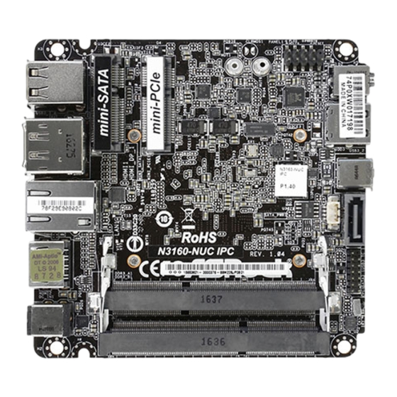
Page 8: Motherboard Layout
PANEL1 AUDIO1 B: USB3 USB3_2 USB3_TC_1 LAN1 SATA_PWR1 SATA3_1 N3160-NUC IPC LPC1 DDR3_A1 (Support DDR3L Only) DC_IN1 DDR3_B1 (Support DDR3L Only) 1 : System Panel Header (PANEL1) 2 : SATA Power Output Connector (SATA_PWR1) 3 : SATA3 Connector (SATA3_1) 4 : LPC Debug Header (LPC1) - Page 9 Backside View: 1 : Power Button 2 : 4 Pin Fan Connector 3 : Battery Connector * Please remove the battery if you want to clear CMOS.
-
Page 10: I/O Panel
1.4 I/O Panel USB 3.1 Ports (USB3_3_4) DC Jack (DC_IN1) DisplayPort (HDMI_DP_1) Infrared LED (IR1) HDMI Port (HDMI1) USB 3.1 Type-C Port (USB3_TC_1) (5V/3A) LAN RJ-45 Port (LAN1)* USB 3.1 Port (USB3_2) HDMI Port (HDMI2) Audio Jack (AUDIO1) * There are two LED next to the LAN port. Please refer to the table below for the LAN port LED indications. -
Page 11: Installation
Chapter 2: Installation Before you install the motherboard, study the configuration of your chassis to ensure that the motherboard fits into it. Make sure to unplug the power cord before installing or removing the motherboard. Failure to do so may cause physical injuries to you and damages to motherboard components. -
Page 12: Installation Of Memory Modules (So-Dimm)
2.3 Installation of Memory Modules (SO-DIMM) N3160-NUC IPC motherboard provides two 204-pin DDR3 (Double Data Rate 3) SO-DIMM slots, which support Dual Channel DDR3L (low voltage). 1. It is not allowed to install a DDR or DDR2 memory module into a DDR3 slot;... -
Page 13: Expansion Slots
2.4 Expansion Slots (mini-PCIe and mini-SATA Slots) There is 1 mini-PCIe slot and 1 mini-SATA slot on this motherboard. mini-PCIe slot: MINI_PCIE1 (mini-PCIe slot; half size) is used for PCI Express mini cards. mini-SATA slot: MINI_SATA1 (mini-SATA slot; full size) is used for mSATA cards. Installing an expansion card Step 1. -
Page 14: Onboard Headers And Connectors
2.5 Onboard Headers and Connectors Onboard headers and connectors are NOT jumpers. Do NOT place jumper caps over these headers and connectors. Placing jumper caps over the headers and connectors will cause permanent damage of the motherboard! SATA Power Output Connector Please connect a SATA power cable to this connector. - Page 15 RESET (Reset Switch): Connect to the reset switch on the chassis front panel. Press the reset switch to restart the computer if the computer freezes and fails to perform a normal restart. PLED (System Power LED): Connect to the power status indicator on the chassis front panel. The LED is on when the system is operating.
-
Page 16: Uefi Setup Utility
Chapter 3: UEFI SETUP UTILITY 3.1 Introduction This section explains how to use the UEFI SETUP UTILITY to configure your system. The UEFI chip on the motherboard stores the UEFI SETUP UTILITY. You may run the UEFI SETUP UTILITY when you start up the computer. Please press <F2>... -
Page 17: Navigation Keys
3.1.2 Navigation Keys Please check the following table for the function description of each navigation key. Navigation Key(s) Function Description Moves cursor left or right to select Screens Moves cursor up or down to select items + / - To change option for the selected items <Enter>... -
Page 18: Advanced Screen
3.3 Advanced Screen In this section, you may set the configurations for the following items: CPU Configu- ration, Chipset Configuration, Storage Configuration, Super IO Configuration, ACPI Configuration, USB Configuration and Platform Trust Technology. Setting wrong values in this section may cause the system to malfunction. -
Page 19: Cpu Configuration
3.3.1 CPU Configuration Intel SpeedStep Technology Intel SpeedStep technology is Intel’s new power saving technology. Pro- cessors can switch between multiple frequencies and voltage points to en- able power saving. The default value is [Enabled]. Configuration options: ® [Enabled] and [Disabled]. If you install Windows OS and want to enable this function, please set this item to [Enabled]. -
Page 20: Chipset Configuration
3.3.2 Chipset Configuration Primary Graphics Adapter Select a primary VGA. Share Memory Configure the size of memory that is allocated to the integrated graphics processor when the system boots up. Onboard HD Audio Select [Auto], [Enabled] or [Disabled] for the onboard HD Audio feature. If you select [Auto], the onboard HD Audio will be disabled when PCI Sound Card is plugged. - Page 21 Good Night LED By enabling Good Night LED, the Power/HDD LEDs will be switched off when the system is on. It will also automatically switch off the Power and Keyboard LEDs when the system enters into Standby/Hibernation mode.
-
Page 22: Storage Configuration
3.3.3 Storage Configuration SATA Controller(s) Use this item to enable or disable the SATA Controller feature. SATA Mode Selection Use this to select SATA mode. The default value is [AHCI Mode]. AHCI (Advanced Host Controller Interface) supports NCQ and other new features that will improve SATA disk perfor- mance but IDE mode does not have these advantages. -
Page 23: Super Io Configuration
3.3.4 Super IO Configuration CIR Controller Enable or disable CIR Controller. -
Page 24: Acpi Configuration
3.3.5 ACPI Configuration PCIE Devices Power On Use this item to enable or disable PCIE devices to turn on the system from the power-soft-off mode. CIR Power On Use this item to enable or disable CIR to power on the system. RTC Alarm Power On Use this item to enable or disable RTC (Real Time Clock) to power on the system. -
Page 25: Usb Configuration
3.3.6 USB Configuration Legacy USB Support Enable or disable Legacy OS Support for USB 2.0 devices. If you encoun- ter USB compatibility issues it is recommended to disable legacy USB support. Select UEFI Setup Only to support USB devices under the UEFI setup and Windows/Linux operating systems only. -
Page 26: Platform Trust Technology
3.3.7 Platform Trust Technology fTPM Enable or disable fTPM. -
Page 27: Hardware Health Event Monitoring Screen
3.4 Hardware Health Event Monitoring Screen In this section, it allows you to monitor the status of the hardware on your system, including the parameters of the CPU temperature, motherboard temperature, CPU fan speed, chassis fan speed, and the critical voltage. CPU Fan 1 Setting Select a fan mode for CPU Fan 1, or choose Customize to set 5 CPU tem- peratures and assign a respective fan speed for each temperature. -
Page 28: Security Screen
3.5 Security Screen In this section, you may set, change or clear the supervisor/user password for the system. Supervisor Password Set or change the password for the administrator account. Only the ad- ministrator has authority to change the settings in the UEFI Setup Utility. Leave it blank and press enter to remove the password. -
Page 29: Boot Screen
3.6 Boot Screen In this section, it will display the available devices on your system for you to config- ure the boot settings and the boot priority. Boot From Onboard LAN Use this item to enable or disable the Boot From Onboard LAN feature. Setup Prompt Timeout This shows the number of seconds to wait for setup activation key. - Page 30 CSM (Compatibility Support Module) Enable to launch the Compatibility Support Module. Please do not disable unless you’re running a WHCK test. If you are using Windows 8.1 64-bit and all of your devices support UEFI, you may also disable CSM for faster boot speed.
-
Page 31: Exit Screen
3.7 Exit Screen Save Changes and Exit When you select this option, it will pop-out the following message, “Save configuration changes and exit setup?” Select [OK] to save the changes and exit the UEFI SETUP UTILITY. Discard Changes and Exit When you select this option, it will pop-out the following message, “Discard changes and exit setup?”... -
Page 32: Software Support
Chapter 4: Software Support 4.1 Install Operating System ® ® This motherboard supports various Microsoft Windows operating systems: 10 32-bit / 10 64-bit / 8.1 32-bit / 8.1 64-bit / 7 32-bit / 7 64-bit. Because mother- board settings and hardware options vary, use the setup procedures in this chapter for general reference only.
Need help?
Do you have a question about the N3160-NUC IPC and is the answer not in the manual?
Questions and answers