
Related Manuals for ZOJE ZJ927 Series


Summary of Contents for ZOJE ZJ927 Series
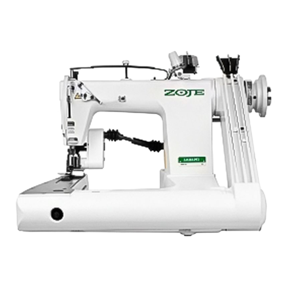
- Page 1 ZJ927/928 HIGH-SPEED FEED-OFF-THE-ARM CHAINSTITCH MACHINE SERIES INSTRUCTION MANUAL AND PARTS LIST...
-
Page 3: Table Of Contents
SAFETY OPERATION Safety symbols and definitions Warning label and show tag Basic concept for safety measures Application and purpose Working environment Safety operation and advert Unpacking and transportation Installation and preparation Operation advert item Maintenance inspection and repair INSTRUCTION MANUAL Warning label and show tag Warning symbol Direction of operation... - Page 4 Ground wire connections Installing the pulley cover Belt tension adjustment Cotton stand Lubrication Checking the machine pulley rotating direction Correct Operation Needles and Threads Installing the Needles Threading the lower threads Threading the upper threads Sewing Thread Tension Adjusting the thread tension Presser Foot Pressure Adjustment Stitch Length Adjustment Cleaning...
- Page 5 Upper thread nipper adjustment Thread release shaft adjustment Lower thread take-up timing adjustment Installing the lapper Puller height adjustment(Machines with puller ) Puller timing adjustment(Machines with puller )
-
Page 6: Safety Operation
SAFETY OPERATION Safety symbols and definition Warning caution symbol:When you are operating the machine,please pay attention to the related parts or devices,to avoid get hurt by these parts or devices. Warning be careful symbol:When the machine is running,please pay attention to the moving parts or devices,to avoid the hands or body get hurt. Earth wire symbol:When the machine is running,please make sure the machine is connecting well with the earth wire. -
Page 7: Basic Concept For Safety Measures
Basic concept for safety measures Application and purpose The industrial sewing machine developed by our company is for improving production's efficiency in sewing business,we don't recommend you to use the sewing machine which is not the same purpose for you sewing. Working environment The machine is not suitable for working in the extremely temperature and humidity environment. -
Page 8: Safety Operation And Advert
Safety operation and advert Unpacking and transportation When the machine is putting or transporting please make sure it is the same direction with the up sign,and unpacking the machine at the top of the carton. When you are taking out the machine from the carton,please don't catch the place which is near of the needle by your hands. -
Page 9: Maintenance Inspection And Repair
You can not put your hands in the moving parts when you want to turn on the electric power. Make sure the machine's turning direction is the same with the turning direction sign before you operate. If the machine have belt cover needle guard ect please make sure they are all installed. Don't let your fingers hair ect near of the needle or moving parts when you are operating the machine. -
Page 10: Instruction Manual
INSTRUCTION MANUEL Warning label and show tag Please follow the instruction on the labels at all times when using the machine.if the labels have been removed or are difficult to read,please contact your nearest Brother dealer. Warning symbol Direction of operation Earth wire symbol Safety devices Finger guard... -
Page 11: Names Of Major Parts
Names of major parts Machine pulley Front cover Presser Needle bar Upper thread nipper Lapper Thread take-up cover Finger guard Pulley cover Machine Specifications Type Specifications Two Needles Two Needles Three Needles Three Needles Thin Materials Medium Materials Medium Materials Heavy Materials 3800 3800... -
Page 12: Work Table And Motor
Work table and motor Work table Common Work table (Servo ) Direct Drive Work table... -
Page 13: Motor And V-Belt
Cotton stand Install Bore Belt Slot Motor stand Install Bore Chain bore Machine connect stand Install bore Cable bore Motor and V-belt CAUTION All cords which are connected to the motor should be secured at least 25mm away from any moving parts. Furthermore,do not excessively bend the cords or secure them too firmly with staples, otherwise there is the danger that fire or electric shocks could occur. -
Page 14: Installation
Installation Installation of sewing machine Use two sets of bolt of M12, mat slice of the inside of the enclosure, the pulley base and the machine mutually allied connect . Reduce three cylinder form earthquake rubber mat to stuff into a machine base, place machine again at the bedplate. - Page 15 (Servo ) Direct Drive machine bedplate press to pack sketch map CAUTION The sewing machine should only be installed by a qualified technician. Ask your Brother dealer or a qualified electrician for any electrical work that may need to be done. The sewing machine weighs more than 49 kg.The installation should be carried out by two or more people.
-
Page 16: Installing The Machine Head
Installing the machine head Install pulley cover base on machine bed with two hexagonal bolts and two washers . Insert two bar cushione into the bottom of the bed. At this time,install the two hexagonal bolts so that they go as far as possible into the notches in the pulley cover base . -
Page 17: Ground Wire Connections
After fastening cushions to the machine bed and pulley cover base with set screws ,fix them to the table with screws . Place the work table so that the machine h- ead is horizontal. If the machina head is not horizontal,lubri- cation will not be carried out correctly. -
Page 18: Belt Tension Adjustment
Place pulley cover A so that it is in bet- ween the eight pulley cover seats ,and t- hen secure it to the pulley cover base with the four screws . Push the belt downward,and then install pulley cover B to pulley cover A with the three screws . -
Page 19: Cotton Stand
Cotton stand Assemble the cotton stand while referring to the cotton stand instruction manual. Install the cotton stand to the cotton stand mounting hole in the work table with nut . Lubrication CAUTION Be sure to wear protective goggles and gloves when handing the lubricating oil gets into your eyes or onto your skin,otherwise inflammation can result. -
Page 20: Checking The Machine Pulley Rotating Direction
Use only the lubricating oil Insert the rubber plug and then close the front cover . Add 1-2 drops of oil once a weed to needle bar bracket lubrication hole . Periodically loose the oil drain screw drain out any oil which collects the front bed oil sump.After draining the oil,tighten the oil drain screw Periodically wipe away any oil which col-... -
Page 21: Correct Operation
Insert the power cord plug into the wall outlet,and then turn on the power switch. I f the direction of rotation is reversed,chan- ge the direction of rotation to the correct di- rection while referring to the instruction m- anual for the motor. For the first 3-4 days of use,do not run the machine at 500 spm lower than the usual speed.This will help contribute to a longer... -
Page 22: Threading The Lower Threads
Threading the lower threads CAUTION Pass the lower threads as shown in the figure below. 3 2 1 Threading the upper threads CAUTION Pass the lower threads as shown in the figure below. -
Page 23: Sewing
Sewing CAUTION Switch the power on step down on pres- ser for lifter pedal ,place a fabric under presser foot,and release presser foot lifter pedal to start the machine . Depress treadle After sewing the work,keep sewing until it reaches thread cutter ,and then cut the threads with thread cutter . -
Page 24: Thread Tension
Thread Tension Adjusting the thread tension Upper thread Good stitches Lower thread Loose , bad stitches Thread tension differs with sewing conditions.Adjust it to suit your particular sewing conditions Less tension More tension Adjust the upper thread tension properly by turning upper thread adjusting screw Adjust the lower thread tension properly by turning lower thread adjusting screw... -
Page 25: Stitch Length Adjustment
Stitch Length Adjustment CAUTION The numerals on the machine pulley scale represent the stitch length(mm) however the actual stitch length will vary depending on the type and thickness of material being used . Open the front cover While pressing the feed adjustment button ,turn the machine pulley toward you slo- wly,(The feed adjustment button will m-... - Page 26 The table below shows samples of stitches made with a highly elastic tabric and a fabric which is not so elastic. Adjust the puller feed by referring to this table. Puller feed Fabric with high elasticity Fabric with low elasticity Correct Feed direction Feed direction...
-
Page 27: Cleaning
Cleaning The following cleaning operations should be carried out each day in order to intain the performance of this machine and to ensure a long service life. CAUTION Daily cheaning Open the looper side plate and clean away any thread scraps and other rubbish . After cleaning,close the looper side plate . -
Page 28: Standard Adjustments
Fill the machine with oil until the oil level reaches the point in between the reference lines on the oil gauge . Close the forward feed arm cover and s- ecure it with the 11 screws . Machines with puller Remove the eight screws ,and then open the puller top cover... -
Page 29: Needles Bar Height Adjustment
Needle bar height adjustment Adjust the heights of the needles At this time,adjust so that each needle is in the center of the needle hole in the needle plate . Remove the screw ,and then remove the presser foot . Turn the machine pulley to drop the needle bar to its lowest position. -
Page 30: Needle And Looper Timing Adjustment
Needle and looper timing adjustment Make an adjustment so that,when needles are down lowest loopers reach the end of their backward travel and the distance from the ne- edle center to the looper tip is 2.7 to 2.9 mm . Remove the presser foot,needle plate and feed dogs. -
Page 31: Timing Of Loopers Running Clear Of Needles
Timing of loopers running clear of needles The loopers run in back of the needle in their forward travel and in front of the needle in th- eir backward travel.Adjust the clearance bet- ween the needles and the loopers to anywhere from 0.05 to 0.10 mm in the forward travel. -
Page 32: Needle Guard Adjustment
Needle guard adjustment The clearance between the needle guard and the needles should be 0.2mm when the stit- ch length is at the minimum setting and the l- oopers are moving toward the needles. The heights should be adjusted to as low a se- tting as possoble without the loopers breaking. -
Page 33: Feed Dog Height Adjustment
Feed dog height adjustment Make an adjustment so that the highest part of the feed dog will be 1.2 mm above the needle plate when feed dog is at the highest position. Adjust the height of feed dog by turning feed Becomes bar eccentric shaft . -
Page 34: Upper Thread Take-Up Thread Guide Adjustment
Upper thread take-up thread guide adjustment Adjust the distance between the center of the upper thread take-up and top of the thread gu- ide will be 6-7mm. Turn the pulley toward yourself until the n- eedle bar is down at the lowest position. Loosen the screw ,and then move the up- per thread take-up thread guide up or do- wn to adjust so that the distance from the... -
Page 35: Thread Release Shaft Adjustment
Thread release shaft adjustment Adjust the thread release shaft so that thread tension discs loosen when the presser foot is raised and tighten when the presser foot is l- owered. Loosen set screw . Make an adjustment by turning thread rel- ease shaft so that the thread tension discs begin to loosen when the presser foot rises 4mm above the top of the needle plate. -
Page 36: Puller Height Adjustment(Machines With Puller )
Adjust felling distance of point A by loosing set screw . After the adjustment,retighten set screw . Adjust felling distance of point B by loosing set screw . After the adjustment,retighten set screw . Puller height adjustment (Machines with puller) Adjust the height of puller so that it is 0.1 to 0.2 mm high from the top of the needle plate. - Page 38 Machine frame components Upper shaft mechanism Needle bar mechanism Presser bar mechanism Feed mechanism Lower shaft mechanism Lopper mechanism Upper threading mechanism Lower threading mechanism Different parts list Gear-box haul material wheel Gear-box Direct drive haul material wheel Double haul material wheel Auto wire cutters device Gas control device Pneumatic device...
-
Page 39: Machine Frame Components
Machine frame components (928) (928-W) (927) - Page 40 Machine frame components 927 Machine frame / 928 Machine frame / PL Machine frame / 2PL Machine frame 928W / 928W Machine frame / Screw SM4.76 Belt Corer Plate Packing Timing Belt Screw SM4.76 Timing Belt Wheel Assy Lower Timing Belt Wheel Assy Upper Timing Belt Wheel Assy Upper Screw SM4.76 Belt Cover...
-
Page 41: Upper Shaft Mechanism
Upper shaft mechanism... - Page 42 Upper shaft mechanism 927Pulley 928Pelley Upper Shaft Ball Bearing Felt Screw SM9.52 Retaining Ring Ball Bearing Washer Bearing Presser Screw SM4.76 Collar Screw M6 Oil Tank Assy Screw SM7.94 O Ring Oil Tank O Ring Oil Gauge Window Oil Gauge Cover Screw SM3.57 Wick Ninpper...
-
Page 43: Needle Bar Mechanism
Needle bar mechanism (928 NEEDLE CLAMP) (927 NEEDLE CLAMP) 22 22 (927 THREAD TAKE-UP CRANK) (928 THREAD TAKE-UP CRANK) - Page 44 Needle bar mechanism / Pin / Wick Ninpper / Rubber Cap / Ball Bearing Connecting Rod Washer Screw SM6.35 Needle Bar Guide Eccentric Wheel Sleeve Needle Bar GuideAssy Screw SM3.57 Wick Ninpper Needle Bar Clamp Screw SM3.57 Rubber Cap Needle Bar Cork Needle Bar Bush,Upper Wick Ninpper Needle Bar Bush,Lower...
-
Page 45: Presser Bar Mechanism
Presser bar mechanism... - Page 46 Presser bar mechanism Adjust Screw Presser Bar Clamp Screw SM5.95 Spring Presser Bar,Lower Presser Bar Presser Bar,Upper Presser Bar, A Presser Bar, B Screw SM4.36 Cover Rubber Cap Rubber Cap Screw SM4.36 Face Plate Facking Presser Bak Lifter Shoulder Screw Shoulder Screw knee Lifter Lever Chain Rod Hook...
-
Page 47: Feed Mechanism
Feed mechanism... - Page 48 Feed mechanism FeedBarEccentricShaft Screw SM5.95 O Ring Feeding Pole Module Eccentric Wheel Sleeve Feeding Pole Eccentric Wheel Sleeve Screw M6 Presser Bak Lifter Push Button Spring Washer O Ring Ring Screw SM5.95 /927 Eccentric Adjuster Eccentric Wheel,Outside Pin,Spring Rachter Stopper Screw Twist Spring Eccentric Wheel,Inside...
-
Page 49: Lower Shaft Mechanism
Lower shaft mechanism... - Page 50 Lower shaft mechanism Lower Shaft Screw SM4.36 Ball Bearing Ball Bearing Ball Bearing Bush Screw M4 Retaining Ring Ball Bearing Bearing Presser Screw SM4.76 Screw SM6.35...
-
Page 51: Lopper Mechanism
Lopper mechanism... - Page 52 Lopper mechanism Screw SM3.57 Front Feed Arm Cap Packing Lopper Peeding Fopk Assy Eccentric Wheel Sleeve Lopper Peeding Fopk Screw SM4.36 Screw SM4.76 Fopk Shaft Bracke Lopper Peeding Fopk Shaft Looper Shaft SetCollar Screw SM4.36 Looper Shaft Looper Shaft Bush,B Looper Shaft Bush,F Screw SM5.95 Looper Lever Pin...
- Page 53 Lopper mechanism...
- Page 54 Lopper mechanism O Ring Screw SM3.57 Ball Bearing Packing 927 Eccentric Wheel /928 Eccentric Wheel Screw SM4.36 Looper Holder,S Screw SM4.36 Looper Holder,L Screw SM3.57 Screw SM3.57 Looper Holder,L Looper Holder,M Looper Holder,R Screw SM3.57 Lapper Guide Plate SM5.95/ Nut SM5.95 SM5.95/ Screw SM5.95...
- Page 55 Upper threading mechanism...
- Page 56 Upper threading mechanism UpperThreadRegulatorAssy Needle Thread Guide Tension Stud Tension Disc Tension Disc Presser Tension Disc Presser Spring Tension Disc Washer Tension Nut Spring Screw SM2.38 Thread Retainer Thread Guide Set Plate Screw SM3.57 Thread Guide Screw SM4.76 Upper Thread Guide Screw SM2.38 Tension Release Shaft UpperThread Tension Bracket...
- Page 57 Upper threading mechanism...
- Page 58 Upper threading mechanism Eccentric Wrench Screw SM5.95 Thread Take-Up Cover Screw SM4.76 Screw SM3.57 Tension Release Lever Tension Release Lever Shaft Screw M4 Shoulder Screw Connecting Rod Short Connecting Rod Tension Release Stud Screw SM5.95 UpperThreadGuideBracket Screw SM3.57 Upper Thread Guide SM3.18-5/ Screw SM3.18 Thread Tension Disc Spring...
-
Page 59: Lower Threading Mechanism
Lower threading mechanism (928) - Page 60 Lower threading mechanism Screw SM2.38 Thread Guide Set Plate Thread Retainer Screw SM3.57 Lower Thread Guide Retainer LowerThreadGuideSupport Screw SM3.57 Inglined Guide Tube Nesting Inglined Guide Tube Assy Inglined Guide Tube Assy Thread Guide Screw SM4.36 L/Tr.Take-UpLeverBracket Lower Thread Guide Screw SM2.38 Lower Thread Presser Thread Release Base...
- Page 61 Lower threading mechanism (928)
- Page 62 Lower threading mechanism Thread Trimmer Looper Cover,Ra Looper Cover,La Looper Cover,Lb Lower Thread Feed BarGuide Nut SM4.36 Thread Retainer Thread Nipper Prop Thread Guide Disc Spring /Nut Arm Thread Guide, M Lower Thread Guide Screw SM3.57...
-
Page 63: Different Parts List
Different parts list 927 Thin Materials / Medium Materials 1/4(6.4mm) PS1/4(6.4mm) 3/16(4.8mm) 1/8(3.2mm) 7/32(5.6mm) PS3/16(4.8mm) PS1/8(3.2mm) Type Needle Clamp 2ZJ104 2ZJ3016 2ZJ108 2ZJ7032 2ZJ104 2ZJ3016 2ZJ108 TVx64#14 TVx64#14 TVx64#14 TVx64#14 TVx64#14 TVx64#14 TVx64#14 Needles Needle Plate 2ZB104 2ZB3016 2ZB108 2ZB7032 2ZB104 2ZB3016 2ZB108... - Page 64 927 Thin Materials / Medium Materials PL1/4(6.4mm) PL3/16(4.8mm) PL1/8(3.2mm) PL7/32(5.6mm) 3/16C(4.8mm) 3/16A(4.8mm) PS7/32(5.6mm) Type Needle Clamp 2ZJ7032 2ZJ104 2ZJ3016 2ZJ108 2ZJ7032 2ZJ3016C 2ZJ3016 TVx64#14 TVx64#14 TVx64#14 TVx64#14 TVx64#14 TVx64#14 TVx64#14 Needles Needle Plate 2ZB7032 2ZB104 2ZB3016 2ZB108 2ZB7032 2ZB3016C 2ZB3016A Presser Foot Assy...
- Page 65 928 Medium Materials / Heavy Materials 1/4(6.4mm) 1/4(6.4mm) PL1/4(6.4mm) PL3/8(9.5mm) PL9/32(7.1mm) PL5/16(7.9mm) PL1/4(6.4mm) Type Thin Materials Medium Materials Medium Materials Heavy Materials Medium Materials Medium Materials Medium Materials Needle Clamp 3ZJ104L 3ZJ104H 3ZJ104H 3PLZJ308H 3PLZJ9032H 3PLZJ5016H 3ZJ104H TVx64#14 TVx5 #18 TVx5 #18 TVx5 #18 TVx5 #18...
- Page 66 928 Medium Materials / Heavy Materials PL3/8(9.5mm) PL9/32(7.1mm) PL5/16(7.9mm) 2PL1/4(6.4mm) 2PL3/8(9.5mm) 2PL9/32(7.1mm) 2PL5/16(7.9mm) Type Heavy Materials Heavy Materials Heavy Materials Medium Materials Medium Materials Medium Materials Medium Materials Needle Clamp 32PLZJ308H 32PLZJ9032H 32PLZJ5016H 3PLZJ308XH 3PLZJ9032XH 3PLZJ5016XH 3ZJ104H TVx5 #21 TVx5 #21 TVx5 #21 TVx5 #18 TVx5 #18...
- Page 67 928 Medium Materials / Heavy Materials 2PL1/4(6.4mm) 2PL3/8(9.5mm) 2PL9/32(7.1mm) 2PL5/16(7.9mm) 2PL1/2(12.7mm) PF/CV1/4(6.4mm) PS1/4(6.4mm) Type Heavy Materials Heavy Materials Heavy Materials Heavy Materials Heavy Materials Heavy Materials Medium Materials Needle Clamp 3ZJ104H 32PLZJ308XH 3PLZJ9032XH 32PLZJ5016XH 32PLZJ102XH 3ZJ104H 3ZJ104H TVx5 #21 TVx5 #21 TVx5 #21 TVx5 #21 TVx5 #21...
- Page 68 928 Medium Materials / Heavy Materials PS3/8(9.5mm) PS9/32(7.1mm) PS5/16(7.9mm) PS1/4(6.4mm) PS3/8(9.5mm) PS9/32(7.1mm) PS5/16(7.9mm) Type Heavy Materials Heavy Materials Heavy Materials Heavy Materials Medium Materials Medium Materials Medium Materials Needle Clamp 3PLZJ308H 3PSZJ9032H 3PLZJ5016H 3ZJ104H 3PLZJ308XH 3PLZJ9032XH 3PLZJ5016XH TVx5 #18 TVx5 #18 TVx5 #18 TVx5 #21 TVx5 #21...
- Page 70 Protect a steel wire Press the feet bridge twist Huang Twist Huang bolt Press the sole twist Huang Twist Huang bolt Press the sole twist Huang Twist Huang bolt Press sole to twist Huang Press sole bolt Roll flower Luo a mother Lock tight bolt Twist Huang bolt Press the sole twist Huang...
- Page 72 / Support / Support bolt / Stalk bolt / Lead a needle piece / Lead a needle piece / Chi bolt / Chi / Nut / Support / Support bolt Lead a needle piece bolt / Lead a needle piece / Lead a needle piece / Nut Support...
- Page 73 Gear-box haul material wheel...
- Page 74 Gear-box haul material wheel Presser Adjust Screw Puller Support Assy Ball Bearing 6.35-6/ Screw SM6.35 Upper Shaft Screw M5 Timing Belt Wheel Assy Upper /Flange Screw SM3.57 Timing Belt Cover,U Timing Belt Timing Belt Wheel Assy Lower Screw Timing Belt Cover,D Screw Washer Puller Bracket...
- Page 76 Timing Belt Wheel Assy Screw M6 Timing Collar Screw M4 /Bearing Cover Ball Bearing Bearing Spacer Eccentric Wheel Shaft Assy Bearing Bush O Ring Oil Seal Screw M6 Packing Puller Device Top Cover Screw M4 O Ring Screw Ring Feed Regurate Button Bush Spring Feed Adjust Button Eccentric Adjuster...
- Page 78 Washer Collar Screw M4 Bearings Ball Bearing Bush Feed Shaft Bush Belt Cover Feed Shaft Universal Joint Shaft Universal coupling guard Universal Joint Assy Screw Timing Belt...
- Page 79 Direct drive haul material wheel...
- Page 80 Direct drive haul material wheel Rear Bush Collar Screw M6 Adjusting Rod Assembly Screw M5 Front Bush Shaft Rubber Cap Calibration Instruction Tablets Axial Screns O Ring Ball parts(Upper) Nut M6 Shaft for linking balls Nut M6-LH Ball parts(Lower) Screw SM3.18 Crank cover Connecting Rod Ball Bearing...
- Page 81 Direct drive haul material wheel...
- Page 82 Direct drive haul material wheel Nut SM5.55 Spring Washer line Cutting Blades Screw SM3.57 Screw SM3.57 Lower Puller Component Lower Puller Bedket Puller Component Retaining Ring Ball Bearing Axial Screw Lower Puller LowerPullerComponentPicture Puller Shaft Upper Puller Stent Ring Rolling Shaft Spring Star Ferry Star Ferry Link...
- Page 83 Double haul material wheel...
- Page 84 Double haul material wheel Lower Wheel Component Lower Wheel Seat Lower Wheel Spring Star Ferry Rolling Shaft Wheel Link One May Pushing Plate Screw M3 Cover Screw SM4.36 Wheel Shaft Pin Ring Upper Wheel Component Star Ferry Link Upper Wheel Upper Wheel Stent Wheel Shaft Front Feed Arm Cap...
- Page 85 Auto wire cutters device (TYPE B) (TYPE A)
- Page 86 Auto wire cutters device Presser Adjust Screw Nut M3 Movable Knife Crest pole Spring Screw M3 Scissors support Spring Pin Spring Movable Knife Component Fixed Knife Component Axial Screns Screw M3 Movable Knife Movable Knife Spring Screw M3 Screw M3.57 Scissors Fix Slice Looper Thread Guide Looper Thread Guide Bracket...
- Page 87 Auto wire cutters device (TYPE B) (TYPE A)
- Page 88 Auto wire cutters device Spring Pin Scissors support 2/ Spring Pin Movable Knife Component Fixed Knife Component Scissors Cover Screw M4X20 Washer Scissors Type A Scissors Type B Mat piece Eliminate a machine Transfer a soft tube Washer 6 Base Base support Crest pole Eliminate a soft tube...
- Page 89 Gas control device...
- Page 90 Gas control device Filter AF1500 Thread Keep APC6-01 0601C/ "L"Connector PL0601C "L"Connector PL0401C Elimination machine BSLM01 Screw M3 Valve 4A110-06 Screw M3 Tube Fill Barometer fix Wood Screw ST4.8 M4-8/ Screw M4 Valve AR1500 PF Wheel Presser Bak Lifter Cape Stent Ball parts Spring Spirit Valve Plate...
- Page 91 Pneumatic device...
- Page 92 Pneumatic device M4-38/ Screw M4 Lamp Screw M3 Screw M6 Washer /Upper Presser Bak Lifter Screw M3 Lower Presser Bak Lifter Valve ASL6-01 Valve HSV06 Cylinder MD32X20 Elimination machine BSLM01 Cylinder Support Nut M10 Buff Pad Screw M4 Presser Bar,Upper Presser Bar "L"Connector PL04M5C SL4-M5/ Valve ASL4-M5...
- Page 93 Pneumatic device...
- Page 94 Pneumatic device Support "Y"transition connector "Y"transition connector 4 Windpipe 6 Windpipe Valve ASL6-M5B Air cock Washer 5...
- Page 95 Servo direct drive device...
- Page 96 Servo direct drive device Control Box Ball Bearing Front Cover Belt Cover Shaft coupling A Shaft coupling Flange HookDrivingShaftSprocket Shaft coupling B Motor Screw M6 Fixed Position Disk Disk Packing Motor Timing Belt Cover Screw M6 Screw M3 Screw M4 Leaf Spring Belt Corer Plate Wood Screw ST4.2...
- Page 97 340x105 270x170 155x120 120x110 58x50...
- Page 98 Chain "S" Hook Screw M6 Washer Screw SM5.95 Cushion Assy Cushion Rubber Spring Washer M6/ Nut M6 Base Cushion 5mm Allen Key 4mm Allen Key 3mm Allen Key 2.5mm Allen Key 2mm Allen Key Screw M12 ScrewDriver(medium) Washer 17-19 Spanner -10Spanner Oiler Oiler...
- Page 99 340x105 270x170 155x120 120x110 58x50...
- Page 100 Chain "S" Hook Screw M6 Washer Screw M6 Fixed Support Cushion Rubber Spring Washer M6/ Nut M6 Base Cushion 5mm Allen Key 4mm Allen Key 3mm Allen Key 2.5mm Allen Key 2mm Allen Key Screw SM4.76 ScrewDriver(medium) Pulley Belt Cover 17-19 Spanner 8-10 Spanner Oiler...
Need help?
Do you have a question about the ZJ927 Series and is the answer not in the manual?
Questions and answers