Advertisement
Quick Links
WEEE Number: 80133970
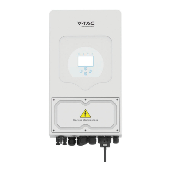
INSTRUCTION MANUAL
HYBRID SOLAR INVERTER
SKU
MODEL
SUN-6K-SG05LP1-EU
11537
MULTI-LANGUAGE MANUAL QR CODE
Please scan the QR code to access the manual in
multiple languages.
IN CASE OF ANY QUERY/ISSUE WITH THE PRODUCT, PLEASE REACH OUT TO US AT: SUPPORT@V-TAC.EU
FOR MORE PRODUCTS RANGE, INQUIRY PLEASE CONTACT OUR DISTRIBUTOR OR NEAREST DEALERS.
V-TAC EUROPE LTD. BULGARIA, PLOVDIV 4000, BUL.L.KARAVELOW 9B
Advertisement

Related Manuals for V-TAC SUN-6K-SG05LP1-EU


Summary of Contents for V-TAC SUN-6K-SG05LP1-EU
- Page 1 Please scan the QR code to access the manual in multiple languages. IN CASE OF ANY QUERY/ISSUE WITH THE PRODUCT, PLEASE REACH OUT TO US AT: SUPPORT@V-TAC.EU FOR MORE PRODUCTS RANGE, INQUIRY PLEASE CONTACT OUR DISTRIBUTOR OR NEAREST DEALERS. V-TAC EUROPE LTD. BULGARIA, PLOVDIV 4000, BUL.L.KARAVELOW 9B...
- Page 2 Contents 1. Safety Introductions ……………………………………………… 2. Product instructions 01-04 ……………………………………………… 2.1 Product Overview 2.2 Product Size 2.3 Product Features 2.4 Basic System Architecture 3. Installation 05-21 …………………………………………………………… 3.1 Parts list 3.2 Mounting instructions 3.3 Battery connection 3.4 Grid connection and backup load connection 3.5 PV Connection 3.6 CT Connection 3.6.1 Meter Connection...
- Page 3 system. for future reference. input short circuits. - 01 -...
- Page 4 - 02 -...
- Page 5 2.2 Product Size - 03 -...
- Page 6 requirements. AC cable DC cable WiFI GPRS Cloud services Cloud services phone Solar Backup Load On-Grid Home Load Grid Battery Smart Load Grid-connected Inverter Grid-connected Inverter Generator - 04 -...
- Page 7 manual - 05 -...
- Page 8 · Not in the cool air directly. ℃ - 06 -...
- Page 9 ≥500mm ≥500mm - 07 -...
- Page 10 Model Wire Size Cable(mm ) Torque value(max) 5.2Nm 5.2Nm - 08 -...
- Page 11 recommended cables. connected. - 09 -...
- Page 12 DIP Switch Inverter BMS 485/ RS 485 DRMs HM G-V G-S ATS240V parallel_1 parallel_2 240V Coil Neutral Earth Bond Batt Temp Gen start-up Sensor N/O Relay CT Coil port. coil relay open contact GV/GS (diesel generator startup signal) - 10 -...
- Page 13 Inverter Temp. sensor - 11 -...
- Page 14 input and output connectors. Model Wire Size Cable(mm ) Torque value(max) 1.2Nm 1.2Nm 1.2Nm 1.2Nm 1.2Nm - 12 -...
- Page 15 GEN PORT LOAD GRID GEN PORT LOAD GRID - 13 -...
- Page 16 unit. Model Wire Size Cable(mm ) - 14 -...
- Page 17 3.6KW- 5KW- 6KW- 7.6KW- 8KW- Inverter Model SG05LP1 SG05LP1 SG05LP1 SG05LP1 SG05LP1 - 15 -...
- Page 18 L N PE L N PE L N PE Load Grid Inverter White wire Black wire Arrow pointing Grid inverter The primary side of the CT needs to be clamped on the Grid live line. *Note: RS485 L N PE L N PE L N PE Load...
- Page 19 L N PE L N PE L N PE RS485 RS485 Load Grid Inverter BMS 485/ RS 485 DRMs Breaker parallel_1 parallel_2 Input Output RS 485 Grid RS485A RS485B EASTRON SDM230 Note: - 17 -...
- Page 20 DC Breaker AC Breaker Load Battery Load DC Breaker Hybrid Inverter AC Breaker AC Breaker AC Breaker Grid Diesel generator Grid E-BAR E-BAR Home Loads DC Breaker AC Breaker Load Do not connect this terminal Battery when the neutral wire and PE Load wire are connected together.
- Page 21 L wire N wire PE wire HM G-V G-S ATS240V coil Inverter relay Inverter open contact ① DC Breaker for battery SUN 3.6K-SG: 150A DC breaker SUN 5K-SG: 150A DC breaker SUN 6K-SG:150A DC breaker SUN 7.6K-SG:225A DC breaker SUN 8K-SG:225A DC breaker GV/GS AC Breaker for Gen port SUN 3.6K-SG: 40A AC breaker...
- Page 22 L wire N wire PE wire Inverter No.3 L N PE L N PE L N PE (slave) BMS 485/ RS 485 Load Grid DRMs Ground parallel_1 parallel_2 Inverter ①②③ DC Breaker for battery ④ SUN 3.6K-SG: 150A DC breaker ①...
- Page 23 -21 -...
- Page 24 4. OPERATION LED Indicator Messages Normal - 22 -...
- Page 25 12/18/2020 09:21:00 1.85 0.04 -1.79 0.02 - 23 -...
- Page 26 Solar Page Solar Graph Grid Page Grid Graph Inverter Page Main Screen Battery Page BMS Page Load Page Load Graph Battery Setting System Work Mode Grid Setting System Setup Gen Port Use Basic Setting Advanced Function Device info - 24 -...
- Page 27 Solar Power: 1560W Today=8.0 KWH PV1-V: 286V PV2-V: 45V Total =12.00 KWH PV1-|: 5.5A PV2-|: 0.0A P1: 1559W P2: 1W Energy Inverter Power: 44W DC-T:52.6C L1: 240V AC-T:41.0C l1:0.6A Load Power: 0W Today=0.0 KWH L: 0V Total =0.40 KWH Energy Grid Stand-by Today=2.2KWH...
- Page 28 Li-BMS Mean Voltage:50.34V Charging Voltage :53.2V Batt Total Current:55.00A Discharging Voltage :47.0V Data Mean Temp :23.5C Charging current :50A Total SOC :38% Discharging current :25A Stand-by Dump Energy:57Ah Details SOC: 36% Data U:50.50V I:-58.02A Li-BMS Power: -2930W Charge Volt Curr Temp Energy Fault...
- Page 29 System Setup System Work Mode Battery Setting Gen Port Grid Setting Basic Advanced Device Info. Setting Function Basic Setting Time Syncs Beep Auto Dim Year Month Basic 2019 Hour Minute 24-Hour out is 7777. Factory Reset Lock out all changes PassWord X--X--X--X CANCEL...
- Page 30 Battery Setting Batt Mode Lithium 400Ah Batt Capacity Batt Mode Use Batt V Max A Charge Use Batt % Max A Discharge No Batt Activate Battery to the system. Battery Setting Start Batt Set2 Gen Charge Grid Charge Gen Signal Grid Signal Gen Force No use,...
- Page 31 Generator Power: 1392W Today=0.0 KWH Total =2.20 KWH L1: 228V Freq:50.0Hz Battery Setting the document Lithium Mode Batt Set3 Shutdown Low Batt Restart resume. Battery Setting Float V Shutdown 53.6V Low Batt Batt Absorption V 57.6V Set3 Restart Equalization V 57.6V TEMPCO(mV/C/Cell) Equalization Days...
- Page 32 System Work Mode 5000 Selling First Max Solar Power Work Zero Export To Load Solar Sell Mode1 Zero Export To CT Solar Sell Max Sell Power Zero-export Power 5000 Energy pattern BattFirst LoadFirst 2. Grid. Grid Peak Shaving 5000 Power Solar Backup Load On-Grid Home Load...
- Page 33 Time Of Use Time Power Batt Work 5:00 5000 49.0V Mode2 9:00 5000 50.2V 13:00 5000 50.9V period. 17:00 5000 51.4V 17:00 21:00 5000 47.1V 21:00 01:00 5000 49.0V Time Of Use Time Power Batt Work 5:00 5000 Mode2 8:00 5000 10:00 5000...
- Page 34 Grid Setting Grid Mode General Standard UL1741 IEEE1547 Grid CPUC RULE21 Set1 SRD-UL-1741 CEI-0-21 Grid Type 220V Single Phase 120/240V Split Phase 120/208V 3 Phase Grid Setting , , Grid Frequency 50HZ 60HZ Grid Set2 Reconnection Time 1.000 area. Grid HZ High Grid Vol High 53.0Hz 265.0V...
- Page 35 Grid Setting Grid Mode General Standard UL1741 IEEE1547 Grid CPUC RULE21 Set1 SRD-UL-1741 CEI-0-21 Grid Type 220V Single Phase 120/240V Split Phase 120/208V 3 Phase Grid Warning Grid Mode: CEI 0-21 Grid Type: 50Hz 220V Single Phase CANCEL Advanced Function Solar Arc Fault ON Backup Delay Func...
- Page 36 Inverter ID : 2012041234 Self-Test OK Testing 59.S1... Test 59.S1 OK! Testing 59.S2... Test 59.S2 OK! Testing 27.S1... Test 27.S1 OK! successfully. Testing 27.S2... Test 27.S2 OK! Testing 81>S1... Test 81>S1 OK! Testing 81>S2... Test 81>S2 OK! Testing 81<S1... Test 81<S1 OK! Testing 81<S2...
- Page 37 GEN PORT USE Mode AC couple on grid side Generator Input AC couple on load side Rated Power PORT Set1 Set1 8000W GEN connect to Grid input On Grid always on SmartLoad Output Power AC Couple Fre High 500W 52.00Hz Micro Inv Input 100% *...
- Page 38 Advanced Function Disable. this is only for factory. Solar Arc Fault ON Backup Delay Func Clear Arc_Fault Set1 System selfcheck Gen peak-shaving CT Ratio ( 2000:1 Signal ISLAND MODE CEI 0-21 Report BMS_Err_Stop Inverter load port shell or bond. Ground cable 230V external relay coil...
- Page 39 Li-BMS Li-BMS Device Info. Inverter ID: 1601012001 Flash Charge Charge Volt Volt Curr Curr Temp Temp Energy Energy Fault Fault HMI: Ver0302 MAIN:Ver 0-5213-0717 Volt Volt Curr Curr 50.38V 19.70A 50.38V 19.70A 30.6C 30.6C 52.0% 52.0% 26.0Ah 26.0Ah 0.0V 0.0V 0.0A 0.0A 0|0|0...
- Page 40 AC cable DC cable Solar Backup Load On-Grid Home Load Grid Battery Smart Load On-Gen+AC couple AC cable DC cable On-Grid Home Load Grid Solar Backup Load Battery On-Grid Inverter On-Load+AC couple AC cable DC cable On-Grid Inverter Backup Load Solar On-Grid Home Load Battery...
- Page 41 On-Grid+AC couple AC cable DC cable Backup Load Solar On-Grid Inverter On-Grid Home Load Battery Grid Smart Load can operate reliably. is as detailed as possible. - 39 -...
- Page 42 Error code 1. When inverter is in Split phase(120/240Vac) or three-phase GFDI _Relay_Failure system (120/208Vac) system, the backup load port N line needs to connect ground; 2. If the fault still exists, please contact us for help. 1. When the grid type and frequency changed it will report F13; 2.
- Page 43 Error code 1. Check the backup load connected, make sure it is in allowed power range; AC Overcurrent fault 2. If the fault still exists, please contact us for help. No Utility 1. Please confirm grid is lost or not; No AC grid 2.
- Page 44 ; ; ; ; ; ; ; product. - 42-...
- Page 45 SUN-3.6K- SUN-5K- SUN-6K- SUN-7.6K- SUN-8K- Model SG05LP1-EU SG05LP1-EU SG05LP1-EU SG05LP1-EU SG05LP1-EU PV String Input Data AC Output Data 5000 6000 7600 3600 5500 6600 3960 Grid Type - 43-...
- Page 46 General Data ℃ ℃ ℃ 5 years - 44 -...
- Page 47 RS485 Pin CAN Pin 1 2 3 4 5 6 7 8 RS485B RS485A CANH CANL RS485A RS485B - 45-...
- Page 48 RS485 Pin 1 2 3 4 5 6 7 8 RS485B RS485A - 46-...
- Page 49 WIFI/RS232 D-GND 12Vdc WIFI/RS232 - 47-...
- Page 50 Ver: 2.2, 2022-10-10 - 48-...
- Page 51 WIFI MODULE FOR SOLAR INVERTER INTRODUCTION Thank you for selecting and buying V-TAC Product. V-TAC will serve you the best. Please read these instructions carefully & keep this user manual handy for future reference. If you have any another query, please contact our dealer or local vendor from whom you have purchased the product.
- Page 52 WARNING 1. Please make sure to turn off the power before starting the installation. 2. Installation must be performed by a qualified electrician. This marking indicates that this Caution, risk of product should not be disposed electric shock. of with other household wastes. NOTICE: Please read this manual carefully before using products and keep it in the place where O&M providers can easily find.
- Page 53 1. WIFI MODULE INSTALLATION Type 1 Step1: Assemble WIFI Module to the inverter communication interface as shown in the diagram. Warning: Please do not hold the WIFI Module body to rotate while install or remove the Module. 2. WIFI MODULE STATUS Check Indicator light Lights Implication...
- Page 54 ABNORMAL STATE PROCESSING If the data on platform is abnormal when the WIFI Module is running, please check the table below and according to the status of indicator lights to complete a simple troubleshooting. If it still can not be resolved or indicator lights status do not show in the table below, please contact Customer Support.
- Page 55 USAGE METHODS AND NOTICES FOR RESET BUTTON Usage methods and key-press descriptions for Reset button Key-press Status Descrip on Light Status Short press 1s SMARTLINK rapid networking status. NET light ashes fast for 100ms. WIFI Module Long press 5s Reboo ng the All lights are ex nguished immediately.
- Page 56 3.Add a Logger Method 1: Enter logger SN manually. Method 2: Click the icon in the right and scan to enter logger SN You can find logger SN in the external packaging or on the logger body. 4.Network Configuration After the logger is added, please configure the network to ensure normal operation.
- Page 57 (5) Shorten the distance between the phone and device. (6) Try to connect to other Wi-Fi. Warning: Please make sure the WIFI Module is working properly before you leave the site. If there is anything abnormal,please do not leave the site and contact customer service: support@v-tac.
Need help?
Do you have a question about the SUN-6K-SG05LP1-EU and is the answer not in the manual?
Questions and answers