Table of Contents
Advertisement
Quick Links
ASSEMBLING AND MAINTENANCE INSTRUCTIONS
Information given as an indication only, and subject to possible modifications
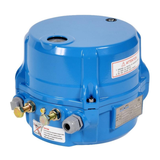
SR 03 PCU ACTUATORS
SR 03 PCU
SECTORIEL S.A.
45, rue du Ruisseau
38290 SAINT QUENTIN-FALLAVIER – FRANCE
Tél : +33 4 74 94 90 70 - Fax : +33 4 74 94 13 95
www.sectoriel.com
/ Email : sectoriel@sectoriel.fr
Pages
1/14
Ref.
IME23070 ENG
Rev.
02
Date
10/2023
Advertisement
Table of Contents

Related Manuals for Sectoriel SR 03 PCU


Summary of Contents for Sectoriel SR 03 PCU
- Page 1 SR 03 PCU ACTUATORS ASSEMBLING AND MAINTENANCE INSTRUCTIONS SR 03 PCU Information given as an indication only, and subject to possible modifications SECTORIEL S.A. Pages 1/14 45, rue du Ruisseau Ref. IME23070 ENG 38290 SAINT QUENTIN-FALLAVIER – FRANCE Rev. Tél : +33 4 74 94 90 70 - Fax : +33 4 74 94 13 95...
- Page 2 2.1 Before any contact with our services, identify the type of actuator. 2.2 SECTORIEL actuators have a 12-month guarantee from the delivery date. Parts recognized as defective by an assessment at our facility, will be replaced at our expense. Complaints generated by incorrect use or a modification of the actuator cannot be taken into account.
-
Page 3: Precautions For Operation
SR 03 PCU ACTUATORS ASSEMBLING AND MAINTENANCE INSTRUCTIONS 3. VERIFICATIONS AND ACCEPTANCE 3.1 At acceptance, check that: - the packaging is in good condition. - the actuator is as ordered. - the equipment is not damaged. 3.2 It is recommended to install the actuator as soon as accepted and not to leave it unused. If the equipment has to be stored, it has to be in a dry place protected from weather. -
Page 4: Manual Intervention
SR 03 PCU ACTUATORS ASSEMBLING AND MAINTENANCE INSTRUCTIONS 6. MANUAL INTERVENTION CAUTION : Before any manual intervention, cut off the power supply, otherwise the SR actuator provided with an electromagnetic clutch, can be damaged. 6.1 Put the hex wrench into the manual socket and turn to CW. -
Page 5: Stop Adjustment
SR 03 PCU ACTUATORS ASSEMBLING AND MAINTENANCE INSTRUCTIONS 7. STOP ADJUSTMENT The return spring of the actuator becomes active in case of emergency stop (a power cut, e.g.) In this case, spring stops have to be adjusted, using stop screws. -
Page 6: Switch Setting
SR 03 PCU ACTUATORS ASSEMBLING AND MAINTENANCE INSTRUCTIONS 8. SWITCH SETTING Limit setting when electrical power isn’t supplied. 8.1 Put the hex wrench into the declutch gear and turn to CW. The declutch gear pops and manual operation is available. The actuator remains the last position during the manual operation without holding the wrench. - Page 7 SR 03 PCU ACTUATORS ASSEMBLING AND MAINTENANCE INSTRUCTIONS Closing/opening limit switch 8.1 The cams ate attached to the drive stem. 8.2 Clockwise rotation = valve closing. The micro-switch closes the actuator. 8.3 Anti-clockwise rotation = valve opening. The micro-switch stops the actuator.
-
Page 8: Electrical Wiring
SR 03 PCU ACTUATORS ASSEMBLING AND MAINTENANCE INSTRUCTIONS 10. ELECTRICAL WIRING 10.1 Separate the cover from the actuator’s body. Unscrew the four bolts. 10.2 Before any electrical connection, check that the electrical diagram provided corresponds to the rating plate. 10.3 Check that the mains voltage corresponds to the voltage mentioned on the rating plate. -
Page 9: Schema De Cablage
SR 03 PCU ACTUATORS ASSEMBLING AND MAINTENANCE INSTRUCTIONS 11. SCHEMA DE CABLAGE Wiring for 230Vac 50Hz voltage Common Phase Manual opening command Manual closing command Fonctioning 4-20 mA Manual and automatic command Opening auxiliary common Closing auxiliary command Auxiliary common Information given as an indication only, and subject to possible modifications SECTORIEL S.A. - Page 10 SR 03 PCU ACTUATORS ASSEMBLING AND MAINTENANCE INSTRUCTIONS Wiring for 24Vcc voltage Common Phase Manual opening command Manual closing command Fonctioning 4-20 mA Manual and automatic common Opening auxiliary command Closing auxiliary command Auxiliary common Information given as an indication only, and subject to possible modifications SECTORIEL S.A.
-
Page 11: Fault Diagnostic
SR 03 PCU ACTUATORS ASSEMBLING AND MAINTENANCE INSTRUCTIONS 12. FAULT DIAGNOSTIC If the actuator does not work properly, check all mechanisms, and look for alignment problems and electrical problems. (See table below) PROBLEM CAUSE SOLUTIONS Blocked worm drive The manual control does not engage... -
Page 12: Control Board
SR 03 PCU ACTUATORS ASSEMBLING AND MAINTENANCE INSTRUCTIONS 13. CONTROL BOARD N° Désignation N° Désignation Do not touch the factory setting Time delay Input setting switch Limit switch connector Auto scan / Span / Zero button Input / Output Do not touch the factory setting... - Page 13 SR 03 PCU ACTUATORS ASSEMBLING AND MAINTENANCE INSTRUCTIONS CONTROL DIP SWITCH F - C Fail close F - O Fail open 3.8 ~ 4.3 : Input fully Close AFULL 19.7 ~ 20.2 : Input fully open Discretion setting Manual setting...
- Page 14 SR 03 PCU ACTUATORS ASSEMBLING AND MAINTENANCE INSTRUCTIONS DIP SWITCH for INPUT Setting Input 4 - 20 mA 2 - 10 V 0 - 5 V 0 - 10 V 1 - 5 v Fail Speed Setting Fail Speed 4 sec...
Need help?
Do you have a question about the SR 03 PCU and is the answer not in the manual?
Questions and answers