Table of Contents
Advertisement
Quick Links
Mounting Guide
ThermoControl - 3
Warning!
Before beginning any work, read this mounting guide
and any associated installation guides. Before starting up the device,
make sure that it is free from defects and in perfect working order.
Always keep these installation instructions to hand near to the device.
Original Mounting Guide
Contents
1. Safety information ................................................................................................................................................................................................................. 2
2. Hazard warnings ..................................................................................................................................................................................................................... 2
3. General Information ............................................................................................................................................................................................................. 3
4. Device overview ...................................................................................................................................................................................................................... 4
5. Mounting points of housing ........................................................................................................................................................................................... 5
6. Installing the controller ...................................................................................................................................................................................................... 6
7. Layout of PCB ............................................................................................................................................................................................................................ 7
8. Overview of terminal blocks ........................................................................................................................................................................................... 8
9. Terminal assignment ............................................................................................................................................................................................................ 9
10. Technical data ...................................................................................................................................................................................................................... 12
Notes .................................................................................................................................................................................................................................................. 13
1
Danfoss District Energy
VM.GU.A1.02
DEN - SMT / PL
Advertisement
Table of Contents

Related Manuals for Danfoss ThermoControl-3


Summary of Contents for Danfoss ThermoControl-3
-
Page 1: Table Of Contents
6. Installing the controller ........................................6 7. Layout of PCB ............................................7 8. Overview of terminal blocks ......................................8 9. Terminal assignment ..........................................9 10. Technical data ............................................12 Notes .................................................. 13 Danfoss District Energy VM.GU.A1.02 DEN - SMT / PL... -
Page 2: Safety Information
After use it should be disposed of via the local recycling collection point. NOTE! This symbol highlights hints that should be observed to ensure efficient, problem-free operation of the system. DEN - SMT / PL VM.GU.A1.02 Danfoss District Energy... -
Page 3: General Information
General Information These installation instructions describe the installation of the electronic domestic hot-water temperature controller ThermoControl-3. You should also always refer to the relevant installation guide for the chosen application. Compliance with all the safety and handling instructions is a requirement for working safely and using the system properly. -
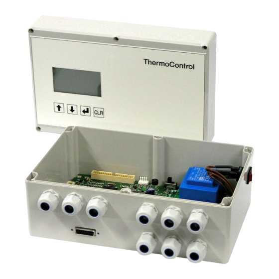
Page 4: Device Overview
(8) 6 x M16 screwed cable entries for mains voltage (4) Membrane key “DOWN in the menu” (power supply, pumps, actuators) (5) Membrane key “OK” (9) Sub-D socket connection 15-pole (not used) (6) Membrane key “Back” DEN - SMT / PL VM.GU.A1.02 Danfoss District Energy... -
Page 5: Mounting Points Of Housing
Mounting Guide ThermoControl – 3 Mounting points of housing Danfoss District Energy VM.GU.A1.02 DEN - SMT / PL... -
Page 6: Installing The Controller
The position of the 5-core ribbon cable is marked, inserting the plug incorrectly causes the membrane keys to malfunction. The 40-core cable is protected against incorrect insertion. Fig.: Positions of the (40-core and 5-core) ribbon cables on the PCB DEN - SMT / PL VM.GU.A1.02 Danfoss District Energy... -
Page 7: Layout Of Pcb
Mounting Guide ThermoControl – 3 Layout of PCB Danfoss District Energy VM.GU.A1.02 DEN - SMT / PL... -
Page 8: Overview Of Terminal Blocks
DF input +12V FWW(FSol / FZWN) DF-input PSol fault PSol GND exDi PZW fault PZW GND PZW 0...10V PZW 0...10V PSL fault PSL GND PSL 0...10V PHZG fault PHZG GND PHZG 0...10V DEN - SMT / PL VM.GU.A1.02 Danfoss District Energy... -
Page 9: Terminal Assignment
Solar storage charging (application MultiHeat) Terminal assignment of additional functions Terminal Name Description Z13, Z14 exDi Initiation of external disinfection or external temperature increase Z15, Z16 Temperature regulator TR or temperature monitor TW Danfoss District Energy VM.GU.A1.02 DEN - SMT / PL... - Page 10 Terminal assignment of inputs and outputs of additional functions Terminal Name Description DF input Input flow sensor pulse generator +12V Flow sensor power supply 12V, maximum 50mA Flow sensor ground 0..10V input not used DEN - SMT / PL VM.GU.A1.02 Danfoss District Energy...
- Page 11 Fused and switched 230V power supply to the pumps Neutral conductor (pumps and valves) Protective earth conductor You will also find the terminal assignment diagram on the inside of the housing cover Danfoss District Energy VM.GU.A1.02 DEN - SMT / PL...
-
Page 12: 10. Technical Data
Interference emission as per EN55011 + A1 : class B Resistance to interference as per EN 61000-6-2 Dimensions (height x width x depth): 159 x 248 x 124 mm Weight 1.6 kg DEN - SMT / PL VM.GU.A1.02 Danfoss District Energy... -
Page 13: Notes
Mounting Guide ThermoControl – 3 Notes Danfoss District Energy VM.GU.A1.02 DEN - SMT / PL... - Page 14 Mounting Guide ThermoControl – 3 Notes DEN - SMT / PL VM.GU.A1.02 Danfoss District Energy...
- Page 15 Mounting Guide ThermoControl – 3 Notes Danfoss District Energy VM.GU.A1.02 DEN - SMT / PL...
- Page 16 Mounting Guide ThermoControl – 3 Danfoss District Energy Division www.danfoss.com VM.GU.A1.02 Produced by Danfoss A/S © 02/2014...
Need help?
Do you have a question about the ThermoControl-3 and is the answer not in the manual?
Questions and answers