Advertisement
Available languages
Available languages
Quick Links
Installation Guide
EvoFlat
AN35894903989801-000101
to the Product
Store
Flat station for single-family, semi-detached and terraced houses as well as flats
Flat station for direct heating and instantaneous domestic hot water. Innovative
self-acting TPC-M controller for control of heating and DHW temperature. Designed
for wall mounting or built in wall.
EvoFlat FSS 1/2/3 — a compact and simple to operate flat station for direct radiator
heating and instantaneous domestic hot water with an innovative self-acting TPC-M
controller for control of heating and DHW temperature. Digit behind the name shows
the type of HEX.
EvoFlat MSS 1/2/3 — a compact and simple to operate flat station for direct heating
with mixing loop and instantaneous domestic hot water with an innovative self-acting
TPC-M controller for control of heating and DHW temperature.
EvoFlat WSS — A fully insulated water heater for flats, single- and multi-family houses.
DHW heating based on flow principle with thermostatic temperature controller.
Innovative, energy-saving controller TCP-M in combination with high performance
heat exchanger for on-demand water heating without no-load losses.
EvoFlat FSF — Apartment station with integrated fresh water system for apartments,
single and multi-family houses. Suitable for heat pumps. Directly heated home station
for heating and DHW using the flow principle. Innovative TCP-M controller and MPHE
heat exchanger for needs-based DHW heating.
Installation must be in compliance with local standards and regula-
tions.
Heat Source (HS) — In the following sections, HS refers to the heat source which sup-
plies the flat stations. A variety of energy sources, such as oil, gas or solar power, could
be used as the primary supply to Danfoss flat stations. For the sake of simplicity, HS can
be taken to mean the primary supply.
Installation
Mounting:
• Adequate space
Please allow adequate space around the flat station for mounting and maintenance
purposes.
• Orientation
The station must be mounted so that components, keyholes and labels are placed
correctly. If you wish to mount the station differently please contact your supplier.
• Drillings
Where flat stations are to be wall-mounted, drillings are provided in the back mount-
ing plate.
• Labelling
Each connection on the flat station is labelled.
Before installation:
• Clean and rinse
Prior to installation, all flat station pipes and connections should be cleaned and
rinsed.
• Thightening
Due to vibration during transport, all flat station connections must be checked and
tightened before installation. Check that all hairpins in click connections are com-
pletely pushed in.
• Unused connections
Unused connections and shut-off valves must be sealed with a plug. Should the
plugs require removal, this must only be done by an authorized service technician.
Installation:
• Strainer
If a strainer is supplied with the station it must be fitted according to schematic
diagram. Please note that the strainer may be supplied loose.
• Connections
Connection to the household installation and district heating pipes connections
must be made using threaded, flanged or welded connections.
The internal connections of the flat station is made by click-fit connections.
Start-up
Start-up, Direct heating
The shut-off valves should be opened and the unit observed as it enters service. Visual
checking should confirm temperatures, pressures, acceptable thermal expansion and
absence of leakage. If the heat exchanger operates in accordance with design, it can
be put to regular use.
After water has been added to the system and the system has been put into operation,
re-tighten ALL connections. Check that all hairpins in click connections are completely
pushed in.
Re-thighten connections
After water has been added to the system and the system has been put
into operation, re-tighten ALL connections. Check that all hairpins in click
connections are completely pushed in.
Start-up, Heating with mixing loop
Start-up:
1: Pump speed
Set the pump to its highest speed of rotation before start-up. On radiator systems, the
selector switch is normally set in "Variable curve / Proportional curve" setting, in "max.
pos. " . For floor heating systems, the selector switch is normally set in "Constant curve"
setting, in "max. pos. " .
Re-thighten connections
After water has been added to the system and the system has been put
into operation, re-tighten ALL connections. Check that all hairpins in click
connections are completely pushed in.
2: Start pump
Start the pump and heat through the system.
Pump
The pump must be switched off during system fill.
3: Open shut-off valves
The shut-off valves should then be opened and the unit observed as it enters service.
Visual checking should confirm temperatures, pressures, acceptable thermal expan-
sion and absence of leakage. If the system operates in accordance with design, it can
be put to regular use, — always taking into account the conditions in the building.
4: Vent system
Switch off the pump and vent the installation after the system has been warmed up.
Please note that some pump types feature a built-in venting function. For others the
installation can be vented by using a vent valve in the flat station or on the radiators,
or, if appropriate, the air valve at the highest point of the system — For additional
information, please refers to the enclosed pump and manual.
5: Adjust pump speed
Set the pump to the lowest possible position, depending on the heating requirement
for the building — taking into account aspects such as cooling and power consump-
tion. If the heating requirement increases the pump setting can be changed by means
of the selector switch. Please refer to the enclosed instruction manual for detailed in-
formation about setting ranges. In the summer, you can switch off the power to the
pump at the mains if you want to save electricity by not heating your home. It should
be ensured that no inappropriate hydraulic situation will occur, when the power to
your pump is turned off. For start-up and venting — see above and the enclosed pump
manual.
To see complete manual use the QR code on the front side.
Safety Notes
Authorized personnel only
Assembly, start-up and maintenance work must be performed by quali-
fied and authorized personnel only.
Please observe instructions carefully
To avoid injury to persons and damage to the device, it is absolutely nec-
to the Pump
essary to read and observe these instructions carefully.
manual
Warning of high pressure and temperature
Be aware of the installation's permissible system pressure and temperature.
The maximum temperature of the flow medium in the flat station is 95 °C.
The maximum operating pressure of the flat station is 10 bar.
The risk of persons being injured and equipment damaged increases
considerably if the recommended permissible operating parameters are
exceeded.
The flat station installation must be equipped with safety valves, however,
always in accordance with local regulations.
Warning of hot surface
The flat station has got hot surfaces, which can cause skin burns.
Please be extremely cautious in close proximity to the flat station.
Power failure can result in the motor valves being stuck in open position.
The surfaces of the flat station can get hot, which can cause skin burns.
The ball valves on district heating supply and return should be closed.
Warning of transport damage
Before flat station installation, please make sure that the flat station has
not been damaged during transport.
IMPORTANT — Tightening of connections
Due to vibrations during transport all flange connections, screw joints
and electrical clamp and screw connections must be checked and tight-
ened before water is added to the system. After water has been added to
the system and the system has been put into operation, re-tighten ALL
connections. Check that all hairpins in click connections are completely
pushed in.
Schematic
FSS
(to see complete manual use the QR code)
DHW
DCW
DCW
HS
Supply
HS
Return
Your flat station might look different than the schematic diagram shown.
WSS
(to see complete manual use the QR code)
DHW
DCW
DCW
40
33
HS
Supply
33
24A
HS
Return
Your flat station might look different than the schematic diagram shown.
Technical parameters
Nominal pressure:
Max. DH supply temperature:
Min. DCW static pressure:
Brazing material (HEX):
Heat exchangers test pressure:
* for station with shunt only
Dimensions (mm)
With connections:
H: 590 × W: 550 × D: 150 (Depth incl. mounting plate).
H: 590 × W: 590 × D: 150 (In gasketed versions).
Connection size
DH, HE, DHW, DCW:
G3/4" ET (int. thread) space 65 mm.
DHW: Capacity examples
DHW
Temperature
capacity
Type
primary
[kW]
37
1
65/19,1
37
1
65/22,4
45
2
65/17,6
45
2
65/20,6
55,5
3
65/14
53
3
65/15,8
42
3
55/16,3
33,7
3
50/19,1
Maintenance
The flat station requires little monitoring, apart from routine checks. It is recommend-
ed to read the energy meter at regular intervals, and to write down the meter readings.
Regular inspections of the flat station according to this Instruction are recommended,
which should include:
Strainers — Cleaning of strainers.
Meters — Checking of all operating parameters such as meter readings.
Temperatures — Checking of all temperatures, such as HS supply temperature and
DHW temperature.
Connections — Checking all connections for leakages.
Safety valves — The operation of the safety valves should be checked by turning the
valve head in the indicated direction.
Venting — Checking that the system is thoroughly vented.
Inspections should be carried out minimum every two years.
Spare parts can be ordered from Danfoss. Please ensure that any enquiry includes the
flat station serial number.
© Danfoss | FEC | 2020.11
MSS
(to see complete manual use the QR code)
DHW
DCW
DCW
HE
HS
Supply
Supply
HE
HS
Return
Return
FSF
(to see complete manual use the QR code)
DHW
HT
HT
DCW
Return
Supply
DCW
40
33
17
7
HS
Supply
33
23
30
24A
7
24A
HS
Return
33
PN10 / PN10 and PN6* / PN10
95 °C
1,0 bar
Cooper and stainless steel
25 bar
Temperature
Flow rate
Flow rate
Pressure
secondary
primary
secondary
loss primary
[°C]
[°C]
[l/h]
[l/h]
[*kpa]
10/45
707
910
16
10/50
762
796
18
10/45
833
1106
18
10/50
890
968
21
10/45
950
1365
41
10/50
950
1140
41
10/45
950
1033
41
10/45
950
829
41
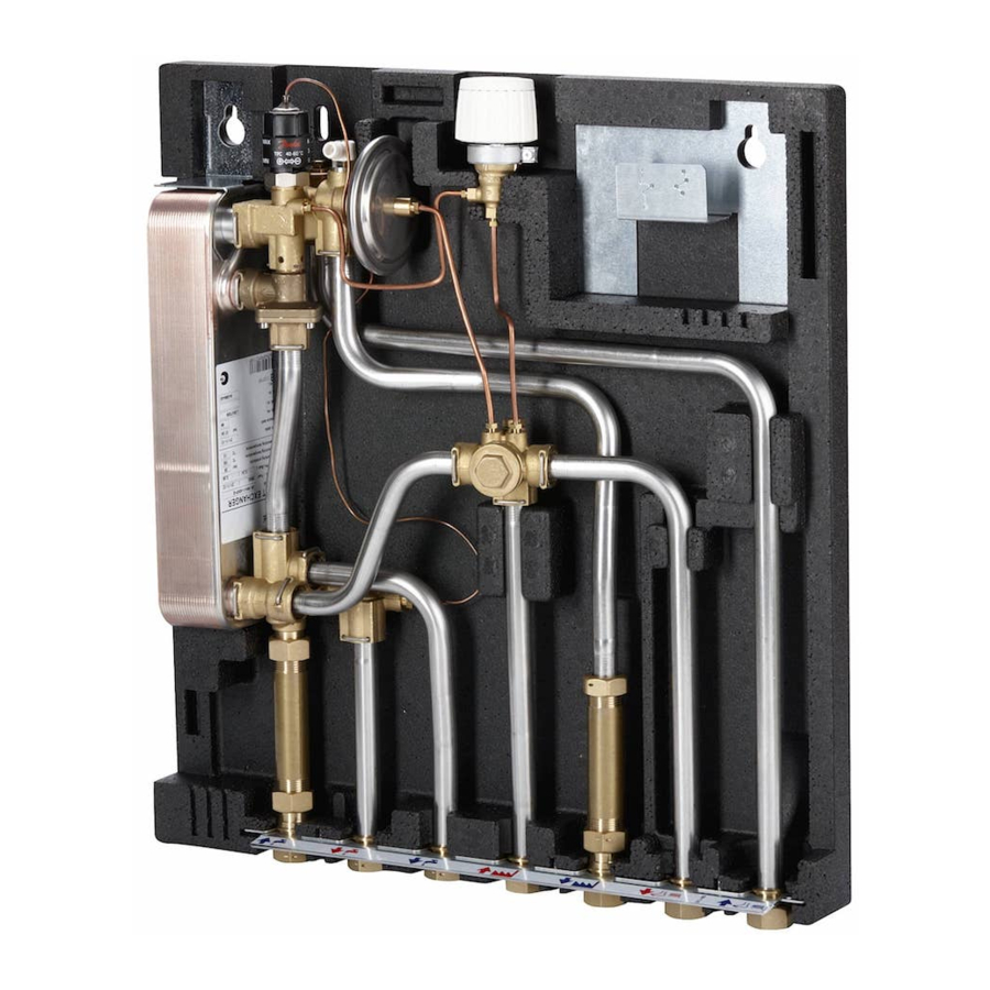
Design, standard
Your flat station might look different than the flatstation shown.
Design description
FSS 1, 2, 3 (left photo):
Plate heat exchanger
2
Strainer
5
21 Return temperature limiter
23 Sensor pocket
24 Fitting piece, energy meter
38 DHW controller type TPM-C
40 Summer by-pass
59 Fitting piece, water meter
Your flat station might look different than the flatstation shown.
Design description
WSS 1, 2, 3 (left photo):
Plate heat exchanger
2
Strainer
5
23 Sensor pocket
HE
Supply
24 Fitting piece for energy meter
38 DHW controller type TPM-C
HE
Return
40 Summer by-pass
59 Fitting piece, water meter
Connections:
1. Domestic cold water (DCW) inlet.
2. Domestic hot water (DHW).
FH
Supply
3. Domestic cold water (DCW) outlet.
FH
Return
4. Primary side (HS) supply.
5. Primary side (HS) return.
6. Heating (HE) supply.
7. Heating (HE) return.
Before making electrical connections, please note the following:
Safety notes — Please read the relevant parts of the safety notes.
230 V — The flat station must be connected to 230 V AC and earth.
Disconnection — The flat station must be electrically connected so that it can be dis-
connected for repairs.
Grounding / potential compensation — The station should be connected to a
grounding point on the right side of the station mounting rail.
Authorized electrician
Electrical connections must be made by an authorized electrician only.
Local standards.
Electrical connections must be made in accordance with current
regulations and local standards.
Troubleshooting in general
In the event of operating disturbances, the following basic features should be checked
before carrying out actual troubleshooting:
• the flat station is connected to electricity,
• the strainer on the HS supply pipe is clean,
• the supply temperature of the HS is at the normal level,
• the differential pressure is equal to or higher than the normal (local) differential pres-
sure in the HS network — if in doubt, ask the HS plant supervisor.
Declaration
EC-DECLARATION OF CONFORMITY
Danfoss A/S
DK-6430 Nordborg
Denmark
declares on our sole responsibility that the product(s)
EvoFlat
Covered by this declaration is in conformity with the following directive(s), standard(s)
or other normative document(s), provided that the product is used in accordance with
our instructions.
EMC – Directive – 2004/108/EC
EN 61000-6-1 2007. Electromagnetic compatibility
— General standard: Immunity for residential,
commercial and light industry.
EN 61000-6-3 2007. Electromagnetic compatibility
— Generic standard: Emission for residential,
commercial & light industry.
Pressure Equipment Directive – 97/23/EC
Equipment category: 0 (article 3.3).
MSS 1, 2, 3 (right photo):
2
Plate heat exchanger
5
Strainer
6
Check valve
10 Circulation pump mixing circuit
23 Sensor pocket
24 Fitting piece, energy meter
29 Actuator
30 Valve HE
38 DHW controller type TPM-C
40 Summer by-pass
59 Fitting piece, water meter
FSF (right photo):
2
Plate heat exchanger
5
Strainer
17 Air valve
23 Sensor pocket for heat meter
24 Fitting piece for heat meter: 3/4" × 110 mm
30 Valve HE
33 Plugs
38 DHW controller type TPM-C
40 Danfoss FJVR for bypass/circulation
59 Fitting piece, cold water meter 3/4" × 110 mm
Machinery Directive 2006/42/EC
EN 14121-1. Safety of machinery — Risk
assessment.
EN 60204-1. Safety of machinery — Electrical
equipment of machines — Part 1: General
requirements.
AN35894903989801-000101
Advertisement

Related Manuals for Danfoss EvoFlat FSS


Summary of Contents for Danfoss EvoFlat FSS
- Page 1 A variety of energy sources, such as oil, gas or solar power, could connections. Check that all hairpins in click connections are completely be used as the primary supply to Danfoss flat stations. For the sake of simplicity, HS can pushed in.
- Page 2 Störfestigkeit für Wohnbereich, Geschäfts- Sicherheit von Maschinen — Elektrische 4: System entlüften Ersatzteile können bei Danfoss bestellt werden. Stellen Sie bitte sicher, dass Sie in Ihrer An- und Gewerbebereiche sowie Kelinbetriebe Ausrüstung von Maschinen — Teil 1: Allge- Pumpe ausschalten und die Station entlüften, nachdem das System auf gewärmt wurde.
Need help?
Do you have a question about the EvoFlat FSS and is the answer not in the manual?
Questions and answers