Advertisement
Quick Links
VQ1000V-TF2Z493EN
ORIGINAL INSTRUCTIONS
Instruction Manual
5 port solenoid valve
Series VQ(C)4000/5000
The intended use of this product is to control the movement on an
actuator.
1 Safety Instructions
These safety instructions are intended to prevent hazardous situations
and/or equipment damage. These instructions indicate the level of
potential hazard with the labels of "Caution," "Warning" or "Danger."
They are all important notes for safety and must be followed in addition
*1)
to International Standards (ISO/IEC)
, and other safety regulations.
*1)
ISO 4414: Pneumatic fluid power - General rules relating to systems.
ISO 4413: Hydraulic fluid power - General rules relating to systems.
IEC 60204-1: Safety of machinery - Electrical equipment of machines.
(Part 1: General requirements)
ISO 10218-1: Robots and robotic devices - Safety requirements for
industrial robots - Part 1: Robots.
• Refer to product catalogue, Operation Manual and Handling
Precautions for SMC Products for additional information.
• Keep this manual in a safe place for future reference.
Caution indicates a hazard with a low level of risk which, if
Caution
not avoided, could result in minor or moderate injury.
Warning indicates a hazard with a medium level of risk
Warning
which, if not avoided, could result in death or serious injury.
Danger indicates a hazard with a high level of risk which, if
Danger
not avoided, will result in death or serious injury.
Warning
• Always ensure compliance with relevant safety laws and
standards.
• All work must be carried out in a safe manner by a qualified person in
compliance with applicable national regulations.
Caution
• The product is provided for use in manufacturing industries only. Do
not use in residential premises.
2 Specifications
2.1 Valve specifications
Metal seal
Rubber seal
Valve Type
5 Port Solenoid Valve
Fluid
Air
Note 1)
Single
0.15 to 1 (0.1 to 1
)
Internal pilot operating
Double
0.15 to 1 (0.1 to 1
Note 1)
pressure range [MPa]
3 position
0.15 to 1
Operating pressure
External
-100 kPa to 1
range
pilot [MPa]
Pilot pressure range
Same as internal pilot operating pressure range
Minimum operating frequency
1 cycle / 30 days
2
20 Hz
VQ(C)4000
position
Maximum
single/
operating
10 Hz
VQ(C)5000
double
frequency
3
10 Hz
VQ(C)4000
position
5 Hz
VQ(C)5000
Duty cycle
Contact SMC
Response time
Refer to catalogue
Flow rate
Refer to catalogue
Ambient/fluid temperature
-10 to +50°C (-5 to +50°C for VQC5000)
2 Specifications - continued
Lubrication
Non-locking Push type, Locking type (Tool
Manual override
Impact/Vibration resistance
Mounting orientation
Enclosure (based on
IEC60529)
Table 1.
Note 1) For VQ(C)5000 metal seal
Note 2) Use dry air to prevent condensation at low temperatures.
Note 3) Impact resistance: No malfunction resulted from the impact test using a
drop impact tester. Test was performed one time each in the axial and right angle
directions of the main valve and armature for both energized and de-energized
states. (Values quoted are for a new valve)
Vibration resistance: No malfunction occurred in a one-sweep test between 45
and 2000 Hz. Test was performed in the axial and right angle directions of the main
valve and armature for both energized and de-energized states. (Values quoted are
for a new valve)
Note 4) Refer to 2.3 for applicable variations.
2.2 Solenoid specifications
Rated coil voltage [VDC]
Allowable voltage fluctuation
Coil insulation type
Power consumption
24 VDC
(Current) [W]
12 VDC
Surge voltage suppressor
Indicator light
Table 2.
Note 1) Valve state is not defined if electrical input is outside the specified operating
range.
2.3 Manifold specifications
2.3.1 VQ4000/5000
VQ400
Series
0
D-sub
IP40
Terminal block
IP65
1)
Electrical entry
box
and ingress
Individual
protection
terminal block kit
(Based on
Lead wire
IP65
IEC60529)
1)
cable
EX123, EX124
1)
IP65
)
Connector
IP65
1(P), 3(R1), 5(R2)
1/2
C6,
C8,
C10,
C12
Port
Side ported
1/4
2(A),4
size
3/8
(B)
N7,
N9,
N11
Bottom
1/4
ported
Table 3.
Note 1) When W type is chosen.
2.3.2 VQC4000/5000
0.2 to 1
Series
VQC4000 VQC5000
)
D-sub,
0.2 to 1
Flat ribbon
IP40
cable,
EX260
EX245
IP65
Electrical entry
EX126
and ingress
EX250
protection
EX260
(Based on
EX500
5 Hz
IEC60529)
EX600
IP67
Lead wire
Circular
connector
3 Hz
Terminal
block box
Note 2)
2 Specifications - continued
Not required
1(P),3(R)
required, Manual)
Note 3)
150/30 m/s²
Port
size
Refer to 3.2 and 7.4
2(A),4(B)
IP40 (IP65 and IP67 compatible)
Note 4)
2(A),4(B
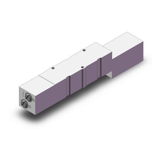
2.4 Indicator light and override positions
In the double solenoid type, A side and B side energization are indicated
by two colours which match the colours of the manual overrides.
Manual override
(Green)
12, 24
(Note 1)
±10 % of rated voltage
Class B or equivalent
0.95 (standard), 0.4 (low wattage)
Figure 1. ON/OFF indicator and override buttons of VQ(C)5000.
0.95 (standard), 0.4 (low wattage)
Varistor
LED
2.5 Pneumatic symbols
Refer to catalogue and special drawings for 'Pneumatic symbols'.
2.6 Special products
Special products (-X) might have specifications different from those
shown in this section. Contact SMC for specific drawings.
3 Installation
3.1 Installation
VQ4000
VQ5000
VQ500
Maximum number of
0
stations (solenoids)
• Do not install the product unless the safety instructions have been read
18 (36)
12 (24)
and understood.
18 (36)
12 (24)
• When using double solenoid type for the first time, actuators may travel
IP40
12 (24)
in an unexpected direction depending on the switching position of the
16 (32)
12 (24)
valve. Implement countermeasures to avoid any danger that may
18 (36)
12 (24)
occur due to the actuator's operation.
16 (32)
3/4
3.2 Environment
3/8
• Do not use in an environment where corrosive gases, chemicals, salt
1/2
water or steam are present.
• Do not use in an explosive atmosphere.
• Do not expose to direct sunlight. Use a suitable protective cover.
1/2
• Do not install in a location subject to vibration or impact in excess of
the product's specifications.
• Do not mount in a location exposed to radiant heat that would result in
temperatures in excess of the product's specifications.
• Products with IP65 and IP67 enclosures (based on IEC60529) are
VQC4000 VQC5000
protected against dust and water; however, these products cannot be
Maximum number of
used in water.
stations (solenoids)
• Products compliant with IP65 and IP67 satisfy the specification through
mounting the product properly. Be sure to read the Specific Product
12 (24)
Precautions for each product
• When using built-in silencer type manifold with an IP67 enclosure,
8 (16)
keep the exhaust port of the silencer from coming in direct contact with
water or other liquids.
• If using in an atmosphere where there is possible contact with water
12 (24)
drop-lets, oil, weld spatter, etc., take suitable preventative measures.
• When the solenoid valve is mounted in a control panel or is energized
for a long time, make sure that the ambient temperature is within the
10 (20)
valve's specified range.
• The metal seal valve is provided with a hole to discharge the pilot EXH.
When using in atmospheres containing water and dust, mount
horizontally.
3 Installation - continued
• Do not use in high humidity environment where condensation can
D
P: 1/2
side:1/2
R: 3/4
U side:
• Contact SMC for altitude limitations.
3/4
C6, C8,
Side
C10, C12
3/8, 1/2
3.3 Piping
ported
1/4
3/8
Bottom
1/4
1/2
ported
• Before connecting piping make sure to clean up chips, cutting oil, dust
Table 4.
• When installing piping or fittings, ensure sealant material does not
• Tighten fittings to the specified tightening torque.
Double solenoid
3.4 Lubrication
Indicator light
Manual override
A: Orange
(Orange)
B: Green
• SMC products have been lubricated for life at manufacture, and do not
• If a lubricant is used in the system, refer to catalogue for details.
3.5 One-touch fittings
When fittings are used, they may interfere with one another depending
Warning
on their types and sizes. Therefore, the dimensions of the fittings to be
used should first be confirmed in their respective catalogues.
3.5.1 Tube attachment and detachment
Refer to the Specific Precautions of Fittings and Tubing in the catalogue.
3.5.2 Precautions on other tube brands
• When using non-SMC brand tubes, refer to the Specific Precautions of
Warning
3.6 Light/Surge voltage suppressor
The valve is fitted with varistor surge suppressors, see Figure 2 and 3.
Refer to 3.8 for Residual voltage value.
3.6.1 Single solenoid
Warning
3.6.2 Double solenoid
SOL
The surge suppressors fitted to the valve are intended to protect the
output device so that the surge generated inside the valve does not affect
the output device. External overvoltage or overcurrent might damage the
surge suppressor, the valve and the output device itself. Additional safety
measures should be taken to prevent the effect of overcurrent on the
valve and connected devices.
occur.
Caution
etc.
enter inside the port. When using seal tape, leave 1 thread exposed
on the end of the pipe/fitting.
Tightening Torque [N∙m]
Connection thread size (R, NPT)
M5
1 to 1.5
1/8
3 to 5
1/4
8 to 12
3/8
15 to 20
1/2
20 to 25
Table 5.
Caution
require lubrication in service.
Caution
Caution
Caution
Fittings and Tubing in the catalogue.
Caution
SOL
LED (orange)
COM: + (-)
Figure 2.
A-side: - (+)
B-side: - (+)
SOL
COM: + (-)
A-side LED (orange)
B-side LED (green)
Figure 3.
Caution
Page 1 of 3
Advertisement

Related Manuals for SMC Networks VQ4000 Series


Summary of Contents for SMC Networks VQ4000 Series
- Page 1 VQ1000V-TF2Z493EN 2 Specifications - continued 2 Specifications - continued 3 Installation - continued ORIGINAL INSTRUCTIONS • Do not use in high humidity environment where condensation can Lubrication Not required P: 1/2 side:1/2 Non-locking Push type, Locking type (Tool 1(P),3(R) occur. Manual override R: 3/4 U side:...
- Page 2 VQ1000V-TF2Z493EN 3 Installation - continued 3 Installation - continued 6 Maintenance - continued 6 Maintenance - continued 3.7 Mounting 3.13 Manual override 6.2 Replacement parts 6.2.3 Plug lead type Caution Warning 6.2.1 Installation/removal of light cover Caution • Regardless of an electric signal for the valve, the manual override is Caution Refer to catalogue for additional information.
- Page 3 VQ1000V-TF2Z493EN 7 Limitations of Use - continued Energy source Single Double 3 position status Spool returns to the Spool stops moving Air supply Spool returns to off off position by air after electricity cut present, position by spring force and spring (Position cannot be electricity cut force...
Need help?
Do you have a question about the VQ4000 Series and is the answer not in the manual?
Questions and answers