Advertisement
Quick Links
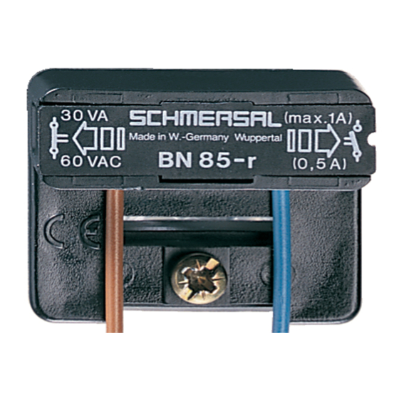
Operating instructions
Magnetic reed switches
Operating instructions. . . . . . . . . . . . .pages 1 to 2
EN
Original
Product description
Plug-in, latching magnetic reed switch for applications that need to be
adjusted at the place of installation. The base is clipped into a C rail.
The shock-sensitive switching element is then plugged in on site and
the switch adjusted.
The NC or NO function depends on the actuating direction and the
polarity of the actuating magnet. The actuators for the magnetic safety
sensors must be ordered separately.
Ordering code
This operating instructions manual applies to the following types:
BN 85 -
-
➀
➁
No.
Option
Description
R
1 bistable contact
➀
➁
Mounting with clamping foot and
2 single wires
1831-1
Mounting to C profile rails and
2 single wires without screws
1831-2
As before with screws
1824-1
Mounting to C profile rails and
sheathed cable without screws
1824-2
As before with screws
1824-3
Mounting with clamping foot and
sheathed cable
Technical data
Standards:
Enclosure:
Operating principle:
Protection class:
Ambient temperature:
Connection type:
- Base:
Sheathed cable LiYY 2 x 0.25 mm² (spec -1824-3)
- Plug-in switching element
Mechanical life:
Electrical life:
Bounce duration
Switching time "Close":
Switching time "Open":
Switching voltage:
Switching current:
Switching capacity:
Withstand voltage:
Resistance to vibration:
Further technical information can be found in the Schmersal
catalogues or in the online catalogue on the Internet:
www.schmersal.net.
The currently valid declaration of conformity can be
downloaded from the internet at www.schmersal.net.
Mounting
Dimensions (All measurements in mm.)
20
40
C rail not included in delivery
- Plug-in reed contact insert, on-site assembly
- Adjustable by releasing the central mounting screw
- Actuating distance up to 40 mm depending on version and actuating
magnet
Contact
Type
1
bistable
BN 85-R
contact
EN
IEC 60947-5-1
glass-fibre reinforced thermoplastic
IP40 to IEC 60529
0°C ... +75°C
2 single wires LiY 0.75 mm
min 10
5 x 10
depending on load
max. 0.07 ms
max. 60 VAC/DC
max. 30 VA/W
60 g on sine wave oscillation
1000
12
Clamping foot
Terminal block
7,5
14
Actuating
Switching distance
magnet
(mm)
BP 6S
2...12
BP 8S
2...10
BP 10S
5...20
2 x BP 10S
6...27
BP 15S
5...22
2 x BP 15S
7...28
BP 34S
10...40
BP 20S
3...28
BP 31S
4...30
BP 11S
4...23
BP 12S
4...27
BN 85
magnetic
2
, 1 m long
9
operations
8
operations
max. 0.2 ms
max. 2 ms
max. 1 A
400 VDC
1
Advertisement

Subscribe to Our Youtube Channel
Related Manuals for schmersal BN 85


Summary of Contents for schmersal BN 85
- Page 1 Withstand voltage: 400 VDC Resistance to vibration: 60 g on sine wave oscillation Further technical information can be found in the Schmersal catalogues or in the online catalogue on the Internet: www.schmersal.net. The currently valid declaration of conformity can be downloaded from the internet at www.schmersal.net.
- Page 2 Operating instructions Magnetic reed switches BN 85 1 bistable contact BN 85-RZ with S actuating magnet BP 10S The electrical connection may only be carried out by authorised personnel in a de-energised condition. The user must observe the country-specific installation standards as well as all prevailing safety regulations and accident prevention rules.
Need help?
Do you have a question about the BN 85 and is the answer not in the manual?
Questions and answers